

Question: 1. Components within digital systems often need to communicate with each other. That is, they often need to transmit data packages from one place to
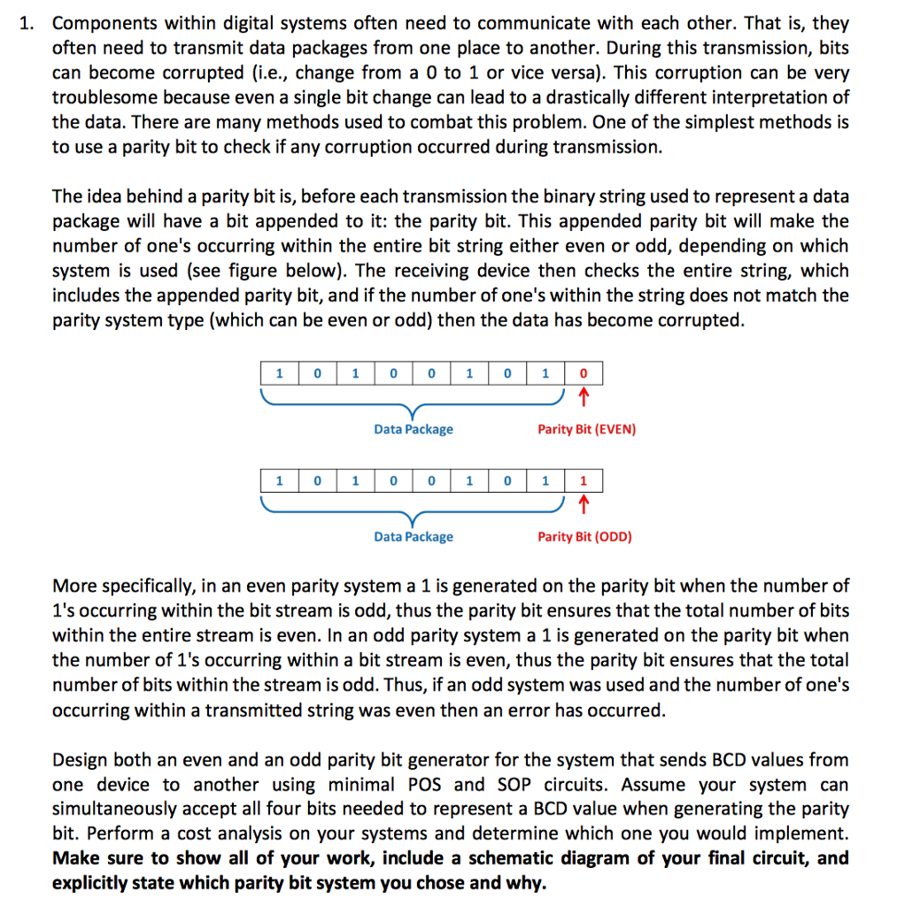
1. Components within digital systems often need to communicate with each other. That is, they often need to transmit data packages from one place to another. During this transmission, bits can become corrupted (i.e., change from a 0 to 1 or vice versa). This corruption can be very troublesome because even a single bit change can lead to a drastically different interpretation of the data. There are many methods used to combat this problem. One of the simplest methods is to use a parity bit to check if any corruption occurred during transmission. The idea behind a parity bit is, before each transmission the binary string used to represent a data package will have a bit appended to it: the parity bit. This appended parity bit will make the number of one's occurring within the entire bit string either even or odd, depending on which system is used (see figure below). The receiving device then checks the entire string, which includes the appended parity bit, and if the number of one's within the string does not match the parity system type (which can be even or odd) then the data has become corrupted. 1 0 10 01 0 10 Data Package Parity Bit (EVEN) 0 0 0 0 Data Package Parity Bit (ODD) More specifically, in an even parity system a 1 is generated on the parity bit when the number of 1's occurring within the bit stream is odd, thus the parity bit ensures that the total number of bits within the entire stream is even. In an odd parity system a 1 is generated on the parity bit when the number of 1's occurring within a bit stream is even, thus the parity bit ensures that the total number of bits within the stream is odd. Thus, if an odd system was used and the number of one's occurring within a transmitted string was even then an error has occurred. Design both an even and an odd parity bit generator for the system that sends BCD values from one device to another using minimal POS and SOP circuits. Assume your system car simultaneously accept all four bits needed to represent a BCD value when generating the parity bit. Perform a cost analysis on your systems and determine which one you would implement. Make sure to show all of your work, include a schematic diagram of your final circuit, and explicitly state which parity bit system you chose and why
Step by Step Solution
There are 3 Steps involved in it

Get step-by-step solutions from verified subject matter experts