

Question: 1 . Consider a 4 - acre detention basin with vertical sides. Assume that thedischarge from the basin is given by Outflow = 7 7
Consider a acre detention basin with vertical sides. Assume that thedischarge from the basin is given by Outflow H where outflow has units of cfs and H is the depth of water in the basin in ftAssume that the basin is able to contain the hydrograph.
Given below is an inflow hydrograph:
Time hrs
Inflow cfs
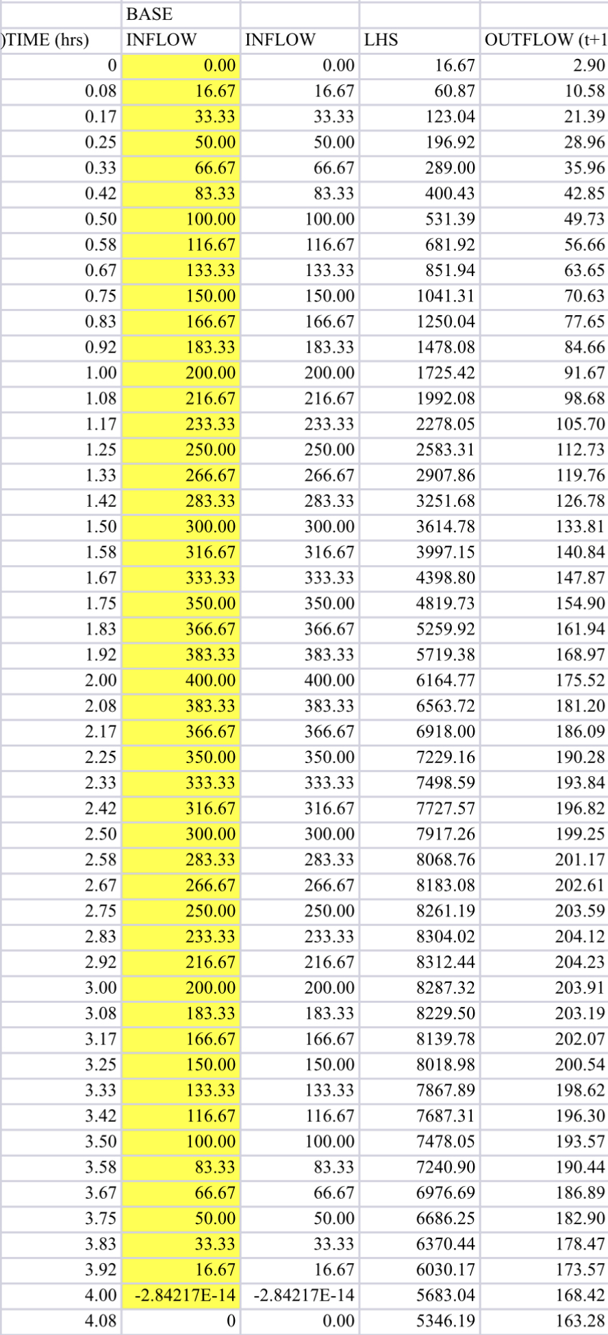
Route the inflow hydrograph through the basin using the storage indication method without use of a computer program or spreadsheet Use a time step of hour. Plot the inflow and outflow hydrographs on the same figure.
Hints:
Write the equation for discharge Q in cfs as a function of stage H in ft
Write the equation for storage S in cfshrs as a function of stage
Using the previous equations, write an equation for storage S as a function of outflow Q
Using the results of step write an equation of St Q as a function of Q where t has units of hours.
The first equation in the storageindication method is
I I St O St O
Each term in the lefthand side of the equation is known. Hence the righthand of the equation is also known.The equation in step can then be used to solve for Q where Q in this case is ORepeat for the subsequent time periods until the first decreasing outflow.
Q H Q in cfs; H in ft
H Q
S H S in acre ft
S H S in cfshrs
S Q
For t hr:
St Q Q Q
From here on the routing is conducted in steps starting with the first two times steps and hr In each step computing the outflow requires solving a quadratic equation. You can Google this if you dont know this
Consider three triangular inflow hydrographs, each with durations of hours. The peak discharges cfs of the hydrographs are and x Using the detention basin from Question and the reservoir routing program provided, route thethree inflow hydrographs.
Note the following:
The program provided uses a minute time step and depth increments of feet.
The inflow factor can be used to obtain the first and third hydrograph.
The outlet code determines which control structure is used. for the orifice and for the weir
The only values you need to change are the inflow factor and the outlet code.Repeat, using the same basin configuration and the following stagedischarge relationship:
Outflow H
Plot the two stagedischarge relationships on the same figure.For each of the three inflow hydrographs, plot on the same figure the inflow hydrograph and the outflow hydrographs corresponding to each of the two stagedischarge relationships. There will be three figures, each with one inflow and two outflow hydrographs.
Give a table with the resulting outflow peaks.
Discuss the results. In particular, explain how and why the relative performance of the outlet structures varies with the hydrograph.
Area acres
Delta T hrs
Scfshrs
Ocfshrs
Outlet Code
Orifice H
Weir H
Inflow factor
Step by Step Solution
There are 3 Steps involved in it
1 Expert Approved Answer
Step: 1 Unlock

Question Has Been Solved by an Expert!
Get step-by-step solutions from verified subject matter experts
Step: 2 Unlock
Step: 3 Unlock