

Question: 1 . Counter - Based FSMs You are tasked with designing a sprinkler system controller for a garden that operates in the following cycle: Watering
CounterBased FSMs
You are tasked with designing a sprinkler system controller for a garden that operates in the following cycle: Watering Zone output W for seconds, Watering Zone output W for seconds, Watering Zone output W for seconds, followed by a rest period output R for seconds before repeating the cycle. The system operates with a clock signal of seconds per period. This pattern will repeat indefinitely.
A How many states, N are needed in a finite state machine FSM to implement this controller? How many states will correspond to watering each of the zones Zone Zone Zone and how many will correspond to the rest period? What is the minimum number of state bits, M required to implement this controller?
B Draw the state diagram for the FSM that implements this controller. Label the states corresponding to watering Zone as ZONEZONE and so on for Zone and Zone Label the rest states as REST REST ldots
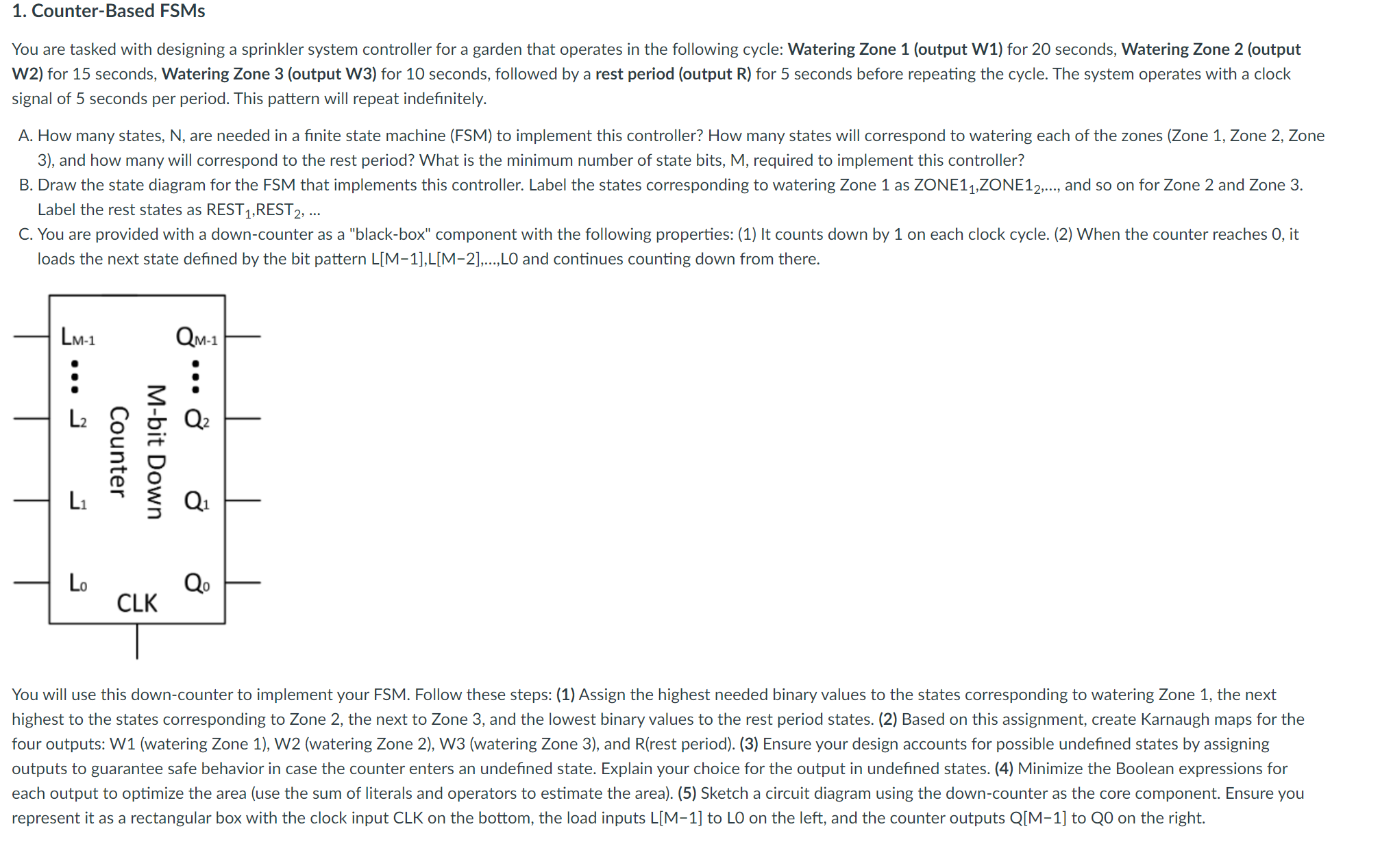
C You are provided with a downcounter as a "blackbox" component with the following properties: It counts down by on each clock cycle. When the counter reaches it loads the next state defined by the bit pattern mathrmLmathrmMmathrmLmathrmMldotsmathrmLO and continues counting down from there.
You will use this downcounter to implement your FSM Follow these steps: Assign the highest needed binary values to the states corresponding to watering Zone the next highest to the states corresponding to Zone the next to Zone and the lowest binary values to the rest period states. Based on this assignment, create Karnaugh maps for the four outputs: Wwatering Zone Wwatering Zone Wwatering Zone and Rrest period Ensure your design accounts for possible undefined states by assigning outputs to guarantee safe behavior in case the counter enters an undefined state. Explain your choice for the output in undefined states. Minimize the Boolean expressions for each output to optimize the area use the sum of literals and operators to estimate the area Sketch a circuit diagram using the downcounter as the core component. Ensure you represent it as a rectangular box with the clock input CLK on the bottom, the load inputs mathrmLmathrmM to LO on the left, and the counter outputs mathrmQmathrmM to QO on the right.
Step by Step Solution
There are 3 Steps involved in it
1 Expert Approved Answer
Step: 1 Unlock

Question Has Been Solved by an Expert!
Get step-by-step solutions from verified subject matter experts
Step: 2 Unlock
Step: 3 Unlock