

Question: Part 1 only required. Only two files need to be edited. Please provide a waveform showing functionality, thanks! Included files ---------------------------------------------------------------------------------- counter.v // Source template
Part 1 only required. Only two files need to be edited. Please provide a waveform showing functionality, thanks!
Included files
----------------------------------------------------------------------------------
counter.v
// Source template for a simple 7-bit binary counter with // enable and synchronous reset.
module count_7(run, CLK, count_out);
output reg [6:0] count_out; input run, CLK;
initial begin count_out = 0; end
always @(posedge CLK) begin if(run == 1'b0) begin // Reset Condition count_out = 0; end
else if (run == 1'b1) begin // Run Condition count_out = count_out+ 1'b1;
else begin count_out = count_out; end end endmodule
binary_bcd.v
module binary_bcd_2(bin_in, digit_1, digit_2); input [6:0] bin_in; output reg [3:0] digit_1; output reg [3:0] digit_2; integer i; always @ (bin_in) begin
digit_1 = 4'd0; digit_2 = 4'd0;
for (i = 6; i >=0; i=i-1) begin
if ( digit_1 >= 5) digit_1 = digit_1 + 3;
if ( digit_2 >= 5) digit_2 = digit_2 + 3;
digit_1 = digit_1
end end endmodule
final_bcd_counter.v
// This is the top module for the programmable BCD counter. // It implements a programmable 7-bit counter and a binary- // to-bcd converter that can output two digits. // // Use of this template is optional
module bcd_count_7(max_count, CLK, run, digit_1, digit_2);
input [6:0] max_count; input CLK, run; output [3:0] digit_1; output [3:0] digit_2;
// TODO: Wires and registers for interconnect if needed
// Programmable 7-bit counter module prog_count_7 counter(.max_count(
// Binary-to-BCD Converter for converting count_out to BCD binary_bcd_2 bcd_converter(.bin_in(
endmodule
prog_counter.v
// Wrapper to add programmability to a 7-bit counter. // This module contains the logic to stop a counter when it // reaches a designated value. The maximum value is 99 (decimal)
module prog_count_7(max_count, run, CLK, count_out)
input [6:0] max_count; input run, CLK; output [6:0] count_out;
// Wires/Registers required go here.
// 7-bit counter instance count_7 counter_1(.run(run), .CLK(CLK), .count_out(count_out));
// TODO: Write logic for Counter control //In your always block, first check if run == 0, then read //max_count. Compare max_count with count_out to stop.
example_bc_count_tb.v (test bench)
// Example BCD Counter Testbench module bcd_count_tb_example;
lab_board.v (not needed)
`timescale 1ns / 1ps
module lab_board(LED, SW, CLK);
output reg [7:0] LED; input [7:0] SW; input CLK;
bcd_count_7 counter( .max_count(SW[6:0]), .CLK(CLK), .run(SW[7]), .digit_l(LED[3:0]), .digit_2(LED[7:4]) );
endmodule
// Inputs reg [6:0] max_count; reg clk, run;
// Outputs wire [3:0] digit_1, digit_2;
// UUT - BCD Counter bcd_count_7 uut(.max_count(max_count), .run(run), .clk(clk), .digit_1(digit_1), .digit_2(digit_2));
// Clock Generator always begin clk = ~clk; #5; end // Simulation initial begin clk = 0; run = 0; max_count = 0; #100; // Set MAX to 73 while run=0 max_count = 73; #10; // Wait, then set run to 1 run = 1; #150; // Change MAX while run is 1 - should NOT affect the output; max_count = 15; #850; // At this time, the output should be 73. Reset it to zero and give it the new max by setting run to 0 run = 0; #20 // Count up to 15 by setting run to 1 run = 1; #50; // Change max count to > 99 max_count = 118; #500 run=0; #20 run=1; // Should count to 99 and stop // *** NOTE*** You will need to simulate 3us to see the entire waveform end endmodule
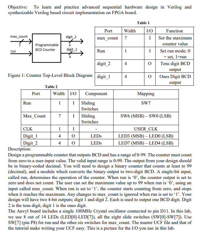
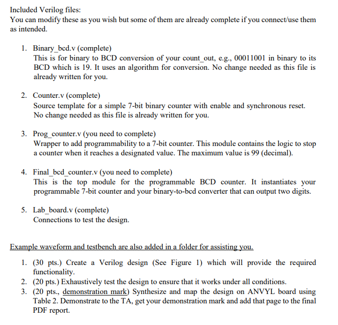
Objective: To learn and practice advanced sequential hardware design in Verilog and synthesizable Verilog based circuit implementation on FPGA board. 4 Table 1 PortW idth 1/0 Function max_count digit_2 max_count TI Set the maximum Programmable counter value BCD Counter digit_1 Run I Set run mode; 0 = set, l=run digit_2 0 Tens digit BCD output Figure 1: Counter Top-Level Block Diagram digit 1 Ones Digit BCD output Table 2 Port W idth 1/0 Component Mapping Run LI Sliding SW7 Switches Max Count 7 1 Sliding SW6 (MSB) - SWO (LSB) Switches CLK USER CLK Digit 1 4 0 LEDs LED3 (MSB) - LEDO (LSB) Digit 2 4 0 LEDS LED7 (MSB) - LED4 (LSB) Description: Design a programmable counter that outputs BCD and has a range of 0-99. The counter must count from zero to a user-input value. The valid input range is 0-99. The output from your design should be in binary-coded decimal. You will need to design a binary counter that counts at least to 99 (decimal), and a module which converts the binary output to two-digit BCD. A single-bit input, called run, determines the operation of the counter. When run is '0', the counter output is set to zero and does not count. The user can set the maximum value up to 99 when run is '0', using an input called max_count. When run is set to '1', the counter starts counting from zero, and stops when it reaches the maximum. Any changes to max_count is ignored when run is set to 'l'. Your design will have two 4-bit outputs, digit 1 and digit 2. Each is used to output one BCD digit. Digit 2 is the tens digit, digit 1 is the ones digit. The Anvyl board includes a single 100MHz Crystal oscillator connected to pin D11. In this lab, we use 8 out of 14 LEDs (LED[0]-LED[7]), all the eight slide switches (SW[0]-SW[7]). Use SW[7] (pin P8) for run and the other six switches for max_count. The master UCF file and that of the tutorial make writing your UCF easy. This is a picture for the I/O you use in this lab. Included Verilog files: You can modify these as you wish but some of them are already complete if you connect/use them as intended. 1. Binary_bcd.v (complete) This is for binary to BCD conversion of your count_out, e.g., 00011001 in binary to its BCD which is 19. It uses an algorithm for conversion. No change needed as this file is already written for you. 2. Counter.v (complete) Source template for a simple 7-bit binary counter with enable and synchronous reset. No change needed as this file is already written for you. 3. Prog_counter.v (you need to complete) Wrapper to add programmability to a 7-bit counter. This module contains the logic to stop a counter when it reaches a designated value. The maximum value is 99 (decimal). 4. Final_bcd_counter.v (you need to complete) This is the top module for the programmable BCD counter. It instantiates your programmable 7-bit counter and your binary-to-bcd converter that can output two digits. 5. Lab_board.v (complete) Connections to test the design. Example waveform and testbench are also added in a folder for assisting you. 1. (30 pts.) Create a Verilog design (See Figure 1) which will provide the required functionality. 2. (20 pts.) Exhaustively test the design to ensure that it works under all conditions. 3. (20 pts., demonstration mark) Synthesize and map the design on ANVYL board using Table 2. Demonstrate to the TA, get your demonstration mark and add that page to the final PDF report. Objective: To learn and practice advanced sequential hardware design in Verilog and synthesizable Verilog based circuit implementation on FPGA board. 4 Table 1 PortW idth 1/0 Function max_count digit_2 max_count TI Set the maximum Programmable counter value BCD Counter digit_1 Run I Set run mode; 0 = set, l=run digit_2 0 Tens digit BCD output Figure 1: Counter Top-Level Block Diagram digit 1 Ones Digit BCD output Table 2 Port W idth 1/0 Component Mapping Run LI Sliding SW7 Switches Max Count 7 1 Sliding SW6 (MSB) - SWO (LSB) Switches CLK USER CLK Digit 1 4 0 LEDs LED3 (MSB) - LEDO (LSB) Digit 2 4 0 LEDS LED7 (MSB) - LED4 (LSB) Description: Design a programmable counter that outputs BCD and has a range of 0-99. The counter must count from zero to a user-input value. The valid input range is 0-99. The output from your design should be in binary-coded decimal. You will need to design a binary counter that counts at least to 99 (decimal), and a module which converts the binary output to two-digit BCD. A single-bit input, called run, determines the operation of the counter. When run is '0', the counter output is set to zero and does not count. The user can set the maximum value up to 99 when run is '0', using an input called max_count. When run is set to '1', the counter starts counting from zero, and stops when it reaches the maximum. Any changes to max_count is ignored when run is set to 'l'. Your design will have two 4-bit outputs, digit 1 and digit 2. Each is used to output one BCD digit. Digit 2 is the tens digit, digit 1 is the ones digit. The Anvyl board includes a single 100MHz Crystal oscillator connected to pin D11. In this lab, we use 8 out of 14 LEDs (LED[0]-LED[7]), all the eight slide switches (SW[0]-SW[7]). Use SW[7] (pin P8) for run and the other six switches for max_count. The master UCF file and that of the tutorial make writing your UCF easy. This is a picture for the I/O you use in this lab. Included Verilog files: You can modify these as you wish but some of them are already complete if you connect/use them as intended. 1. Binary_bcd.v (complete) This is for binary to BCD conversion of your count_out, e.g., 00011001 in binary to its BCD which is 19. It uses an algorithm for conversion. No change needed as this file is already written for you. 2. Counter.v (complete) Source template for a simple 7-bit binary counter with enable and synchronous reset. No change needed as this file is already written for you. 3. Prog_counter.v (you need to complete) Wrapper to add programmability to a 7-bit counter. This module contains the logic to stop a counter when it reaches a designated value. The maximum value is 99 (decimal). 4. Final_bcd_counter.v (you need to complete) This is the top module for the programmable BCD counter. It instantiates your programmable 7-bit counter and your binary-to-bcd converter that can output two digits. 5. Lab_board.v (complete) Connections to test the design. Example waveform and testbench are also added in a folder for assisting you. 1. (30 pts.) Create a Verilog design (See Figure 1) which will provide the required functionality. 2. (20 pts.) Exhaustively test the design to ensure that it works under all conditions. 3. (20 pts., demonstration mark) Synthesize and map the design on ANVYL board using Table 2. Demonstrate to the TA, get your demonstration mark and add that page to the final PDF report
Step by Step Solution
There are 3 Steps involved in it

Get step-by-step solutions from verified subject matter experts