

Question: 1. Create a circuit project Lab1.circ in the Logisim. 2. Add a circuit testing D-Flip-Flop 3. Add a circuit testing a 4-1 Multiplexer 4. Build
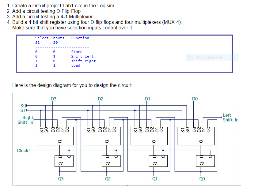
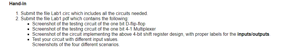
1. Create a circuit project Lab1.circ in the Logisim. 2. Add a circuit testing D-Flip-Flop 3. Add a circuit testing a 4-1 Multiplexer 4. Build a 4-bit shift register using four D-flip-flops and four multiplexers (MUX-4). Make sure that you have selection inputs control over it. Select Inputs S1 so Function 0 @ 0 1 Store Shift left shift right Load Rectangular Snip 1 1 1 Here is the design diagram for you to design the circuit: D3 D2 D1 DO SOH S1 Right Shift In Left Shift In D2H D1i DC mo Q Q o Q Clock TQ 0 QD 8100 9 Q3 Hand-In 1. Submit the file Lab1.circ which includes all the circuits needed 2. Submit the file Lab1.pdf which contains the following: Screenshot of the testing circuit of the one bit D-flip-flop Screenshot of the testing circuit of the one bit 4-1 Multiplexer Screenshot of the circuit implementing the above 4-bit shift register design, with proper labels for the inputs/outputs. Test your circuit with different input values. Screenshots of the four different scenarios. 1. Create a circuit project Lab1.circ in the Logisim. 2. Add a circuit testing D-Flip-Flop 3. Add a circuit testing a 4-1 Multiplexer 4. Build a 4-bit shift register using four D-flip-flops and four multiplexers (MUX-4). Make sure that you have selection inputs control over it. Select Inputs S1 so Function 0 @ 0 1 Store Shift left shift right Load Rectangular Snip 1 1 1 Here is the design diagram for you to design the circuit: D3 D2 D1 DO SOH S1 Right Shift In Left Shift In D2H D1i DC mo Q Q o Q Clock TQ 0 QD 8100 9 Q3 Hand-In 1. Submit the file Lab1.circ which includes all the circuits needed 2. Submit the file Lab1.pdf which contains the following: Screenshot of the testing circuit of the one bit D-flip-flop Screenshot of the testing circuit of the one bit 4-1 Multiplexer Screenshot of the circuit implementing the above 4-bit shift register design, with proper labels for the inputs/outputs. Test your circuit with different input values. Screenshots of the four different scenarios
Step by Step Solution
There are 3 Steps involved in it

Get step-by-step solutions from verified subject matter experts