

Question: 1) Create an equivalent Algorithmic State Chart representation, using rectangular boxes to show states, diamonds to show input/decision blocks, and ovals to represent conditional outputs.
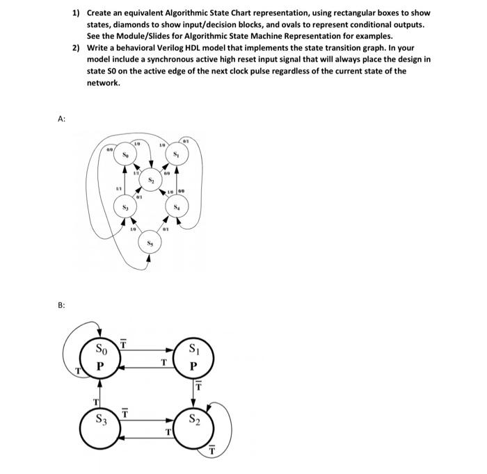
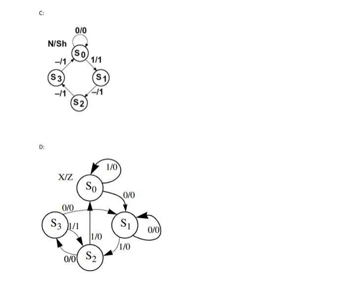
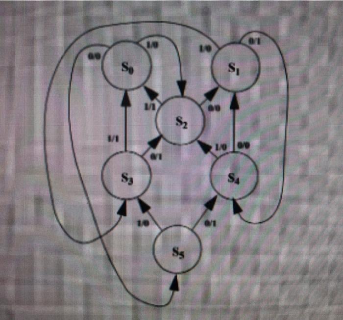
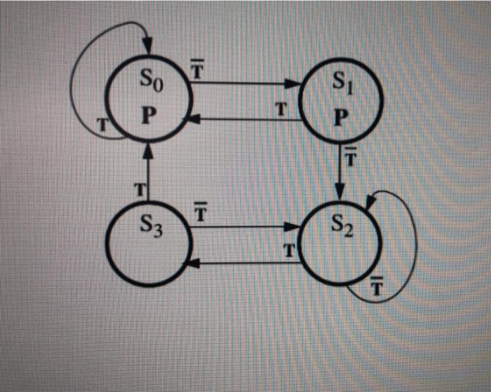
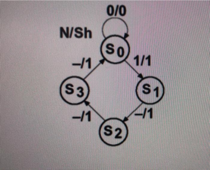
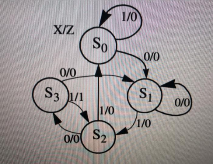
1) Create an equivalent Algorithmic State Chart representation, using rectangular boxes to show states, diamonds to show input/decision blocks, and ovals to represent conditional outputs. See the Module/Slides for Algorithmic State Machine Representation for examples. 2) Write a behavioral Verilog HDL model that implements the state transition graph. In your model include a synchronous active high reset input signal that will always place the design in state So on the active edge of the next clock pulse regardless of the current state of the network. A: 1 10 S, 11 100 1 B: IT So P T Si P T S3 S2 T T C: 0/0 N/Sh (SO) -11 1/1 (53) (S1 -/1 -11 (S2 D: 1/0 XIZ So 0/0 0/0 S3 1/1 Si 0/0) 1/0 1/0 0/0 S2 1) Create an equivalent Algorithmic State Chart representation, using rectangular boxes to show states, diamonds to show input/decision blocks, and ovals to represent conditional outputs. See the Module/Slides for Algorithmic State Machine Representation for examples. 2) Write a behavioral Verilog HDL model that implements the state transition graph. In your model include a synchronous active high reset input signal that will always place the design in state SO on the active edge of the next clock pulse regardless of the current state of the network. TAD S, he Sy SA T Si So P T P T T T S3 S2 T 0/0 N/Sh SO -/1 1/1 S3 S1 -11 -11 S2 1/0 XIZ So 0/0 0/0 S3 1/1 Si 0/0) 1/0 1/0 0/0 S2 1) Create an equivalent Algorithmic State Chart representation, using rectangular boxes to show states, diamonds to show input/decision blocks, and ovals to represent conditional outputs. See the Module/Slides for Algorithmic State Machine Representation for examples. 2) Write a behavioral Verilog HDL model that implements the state transition graph. In your model include a synchronous active high reset input signal that will always place the design in state So on the active edge of the next clock pulse regardless of the current state of the network. A: 1 10 S, 11 100 1 B: IT So P T Si P T S3 S2 T T C: 0/0 N/Sh (SO) -11 1/1 (53) (S1 -/1 -11 (S2 D: 1/0 XIZ So 0/0 0/0 S3 1/1 Si 0/0) 1/0 1/0 0/0 S2 1) Create an equivalent Algorithmic State Chart representation, using rectangular boxes to show states, diamonds to show input/decision blocks, and ovals to represent conditional outputs. See the Module/Slides for Algorithmic State Machine Representation for examples. 2) Write a behavioral Verilog HDL model that implements the state transition graph. In your model include a synchronous active high reset input signal that will always place the design in state SO on the active edge of the next clock pulse regardless of the current state of the network. TAD S, he Sy SA T Si So P T P T T T S3 S2 T 0/0 N/Sh SO -/1 1/1 S3 S1 -11 -11 S2 1/0 XIZ So 0/0 0/0 S3 1/1 Si 0/0) 1/0 1/0 0/0 S2
Step by Step Solution
There are 3 Steps involved in it

Get step-by-step solutions from verified subject matter experts