

Question: 1 . Each group will hand in one project. 2 . Projects must be neatly presented in a folder. Write / draw on one side
Each group will hand in one project.
Projects must be neatly presented in a folder. Write draw on one side of the page only.
The cover page must include the course code, title of project, date, group number and list of group
members initials last name, and student number
Each calculation must have a corresponding neat sketch. All relevant dimensions, section sizes etc.
must be given, with a title on the drawing.
PROJECT BRIEF
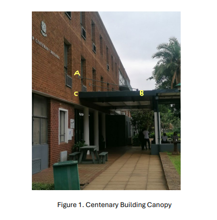
Figure below shows the canopy at the entrance of Centenary Building.
The structure supports roof sheeting, and is supported by a system of steel beams at C and B These
loads are then transferred from the beams to the columns, to the foundations and into the ground. Tie
rods are attached to the wall at Point A and to the beam at Point B as shown in the idealised Sketch in
Figure
For the kN load at Joint B:
Determine the member forces and normal stresses in members AB and BC
Calculate the deflection of the tie AB
Determine the strain in the tie.
Check if the strength of the tie is sufficient if it is made of Grade SJR steel with Minimum Yield
Strength of MPa and Ultimate Strength of MPa.
If the connections at points A B and C consist of a single bolt diameter mm with plates on
either side, calculate the shear stress in the bolt at point Arefer to Figure for detail
SECTION PROPERTIES Refer to the Figure Centenary Building Canopy steel section tables for your section properties Figure Idealised sketch of Canopy
Fig. a Top View of Bolt Connection
Fig. b Side View of Bolt Connection
Tie Rod AB: x Hollow Circular Tube
Beam BC: x x Rectangular Hollow Section
Esteel x MPa
Step by Step Solution
There are 3 Steps involved in it
1 Expert Approved Answer
Step: 1 Unlock

Question Has Been Solved by an Expert!
Get step-by-step solutions from verified subject matter experts
Step: 2 Unlock
Step: 3 Unlock