

Question: 1 - Eccentric speed reducer The figure below shows a schematic representation of an eccentric speed reducer along with a kinematic model. The input
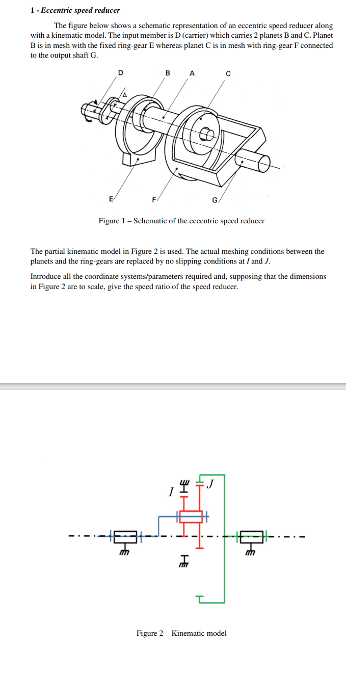
1 - Eccentric speed reducer The figure below shows a schematic representation of an eccentric speed reducer along with a kinematic model. The input member is D (carrier) which carries 2 planets B and C. Planet B is in mesh with the fixed ring-gear E whereas planet C is in mesh with ring-gear F connected to the output shaft G. B A E F Figure 1 - Schematic of the eccentric speed reducer The partial kinematic model in Figure 2 is used. The actual meshing conditions between the planets and the ring-gears are replaced by no slipping conditions at I and J. Introduce all the coordinate systems/parameters required and, supposing that the dimensions in Figure 2 are to scale, give the speed ratio of the speed reducer. HH J H Figure 2- Kinematic model
Step by Step Solution
There are 3 Steps involved in it

Get step-by-step solutions from verified subject matter experts