

Question: 1. Figure 1 represents a pipe network in a small community. Water enters the pipe network at junction A from a water storage tower
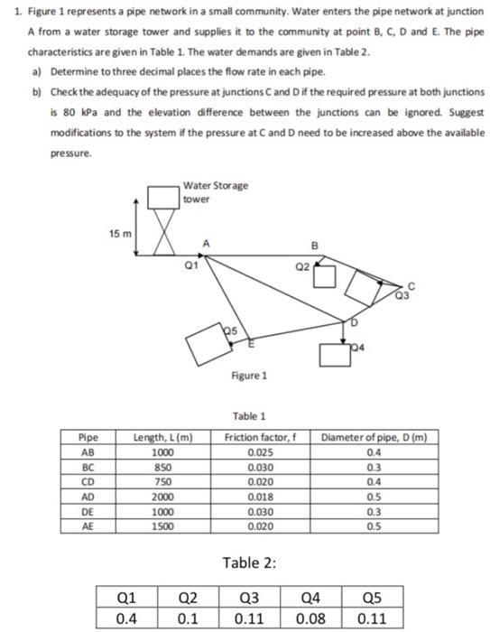
1. Figure 1 represents a pipe network in a small community. Water enters the pipe network at junction A from a water storage tower and supplies it to the community at point B, C, D and E. The pipe characteristics are given in Table 1. The water demands are given in Table 2. a) Determine to three decimal places the flow rate in each pipe. b) Check the adequacy of the pressure at junctions C and D if the required pressure at both junctions is 80 kPa and the elevation difference between the junctions can be ignored. Suggest modifications to the system if the pressure at C and D need to be increased above the available pressure. Water Storage tower 15 m Q1 Q2 Figure 1 Table 1 Pipe Length, L(m) Friction factor, f Diameter of pipe, D (m) AB 1000 0.025 0.4 BC 850 0.030 0.3 CD 750 0.020 0.4 AD 2000 0.018 0.5 DE 1000 0.030 0.3 AE 1500 0.020 0.5 Table 2: Q1 Q2 Q3 Q4 Q5 0.4 0.1 0.11 0.08 0.11
Step by Step Solution
3.54 Rating (164 Votes )
There are 3 Steps involved in it

Get step-by-step solutions from verified subject matter experts