

Question: ( 1 ) / ( - = ) Figure: H - bridge inverter circuit configuration for a transformerless PV inverter system connecting to a grid.
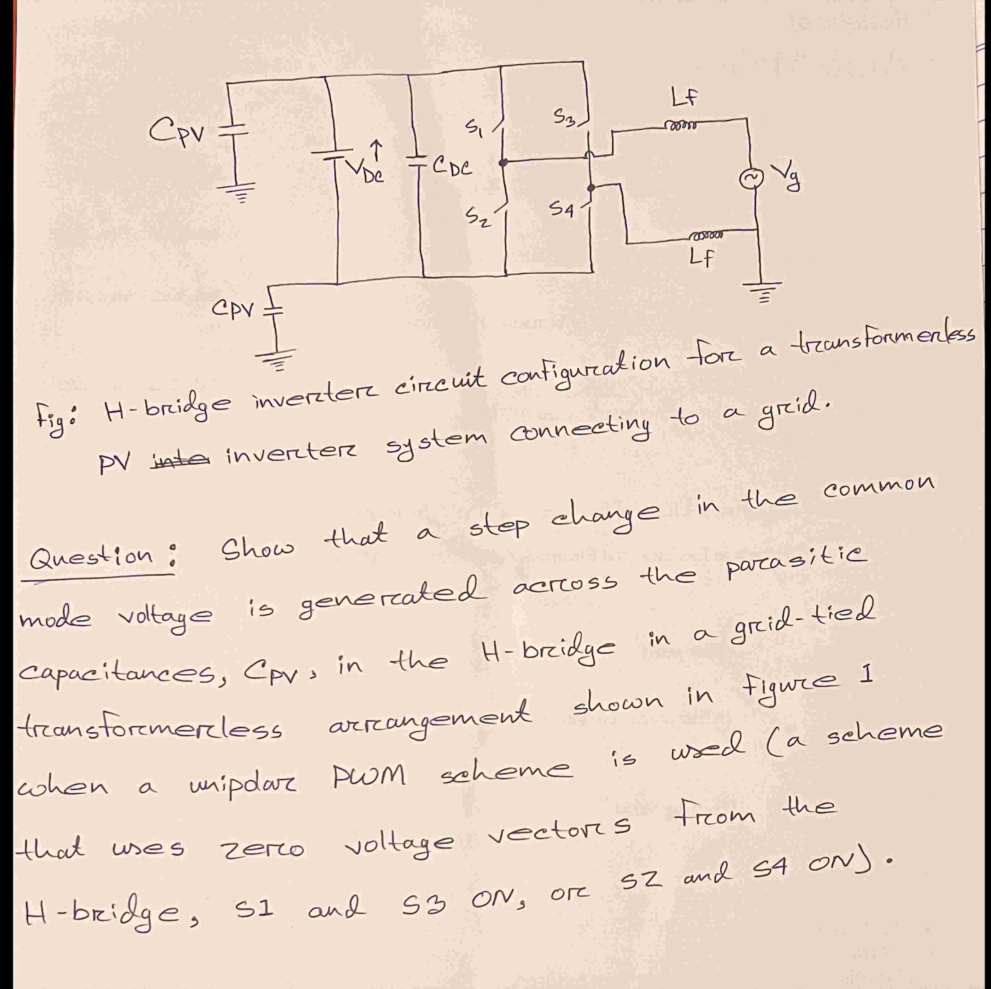
Figure: Hbridge inverter circuit configuration for a transformerless PV inverter system connecting to a grid.
Question: Show that a step change in the common mode voltage is generated across the parasitic capacitances, CPV in the Hbridge in a gridtied transformerless arrangement shown in figure when a unipolar PWM scheme is used a scheme that uses zero voltage vectors from the Hbridge, S and S ON or S and S on
Step by Step Solution
There are 3 Steps involved in it
1 Expert Approved Answer
Step: 1 Unlock

Question Has Been Solved by an Expert!
Get step-by-step solutions from verified subject matter experts
Step: 2 Unlock
Step: 3 Unlock