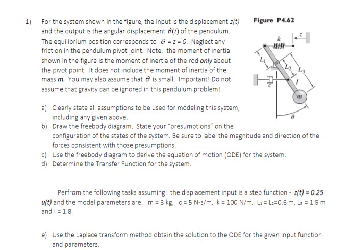
Question: 1) For the system shown in the figure, the input is the displacement z(t) Figure P4.62 and the output is the angular displacement e() of

1) For the system shown in the figure, the input
1) For the system shown in the figure, the input is the displacement z(t) Figure P4.62 and the output is the angular displacement e() of the pendulum. The equilibrium position corresponds to @ = z = 0. Neglect any k friction in the pendulum pivot joint. Note: the moment of inertia shown in the figure is the moment of inertia of the rod only about the pivot point. It does not include the moment of inertia of the mass m. You may also assume that @ is small. Important! Do not assume that gravity can be ignored in this pendulum problem! a) Clearly state all assumptions to be used for modeling this system, including any given above. b) Draw the freebody diagram. State your "presumptions" on the configuration of the states of the system. Be sure to label the magnitude and direction of the forces consistent with those presumptions. c) Use the freebody diagram to derive the equation of motion (ODE) for the system. d) Determine the Transfer Function for the system. Perfrom the following tasks assuming: the displacement input is a step function - z(t) = 0.25 u(t) and the model parameters are: m = 3 kg, c= 5 N-s/m, k = 100 N/m, L: = L:=0.6 m, Ly = 1.5 m and 1 = 1.8 e) Use the Laplace transform method obtain the solution to the ODE for the given input function and parameters

Step by Step Solution

There are 3 Steps involved in it

1 Expert Approved Answer
Step: 1 Unlock blur-text-image
Question Has Been Solved by an Expert!

Get step-by-step solutions from verified subject matter experts

Step: 2 Unlock
Step: 3 Unlock

Students Have Also Explored These Related Mathematics Questions!