

Question: 1 - Frame Load Analysis The figure below shows a floor crane with electric winch with solid plastic wheels used for lifting and moving loads.
Frame Load Analysis
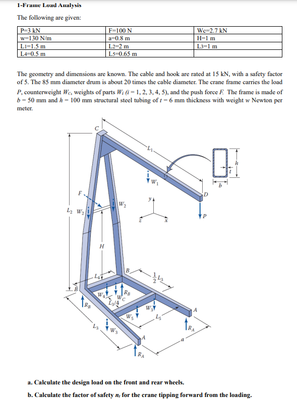
The figure below shows a floor crane with electric winch with solid plastic wheels used for lifting and
moving loads. It has electric power capacity to lift a load P The concrete or sand counterbalance
weight W on the base prevents the crane from tipping forward when the crane is pushed by a horizontal
force F acting at a height H from the ground. For safety purposes, the drive system includes a torque
limiter coupled to a drum and allows the crane to lift no more than the working load P
The following are given:
P kN
F N
Wc kN
w Nm
a m
H m
L m
L m
L m
L m
L
The geometry and dimensions are known. The cable and hook are rated at kN with a safety factor
of The mm diameter drum is about times the cable diameter. The crane frame carries the load
counterweight weights of parts and the push force The frame is made of
and structural steel tubing of thickness with weight Newton per
meter.
a Calculate the design load on the front and rear wheels.
b Calculate the factor of safety for the crane tipping forward from the loading.
Step by Step Solution
There are 3 Steps involved in it
1 Expert Approved Answer
Step: 1 Unlock

Question Has Been Solved by an Expert!
Get step-by-step solutions from verified subject matter experts
Step: 2 Unlock
Step: 3 Unlock