

Question: 1 . Lead compensator: Consider a second - order plant model given by ( G ( s ) = frac { 4 0
Lead compensator: Consider a secondorder plant model given by Gsfracss
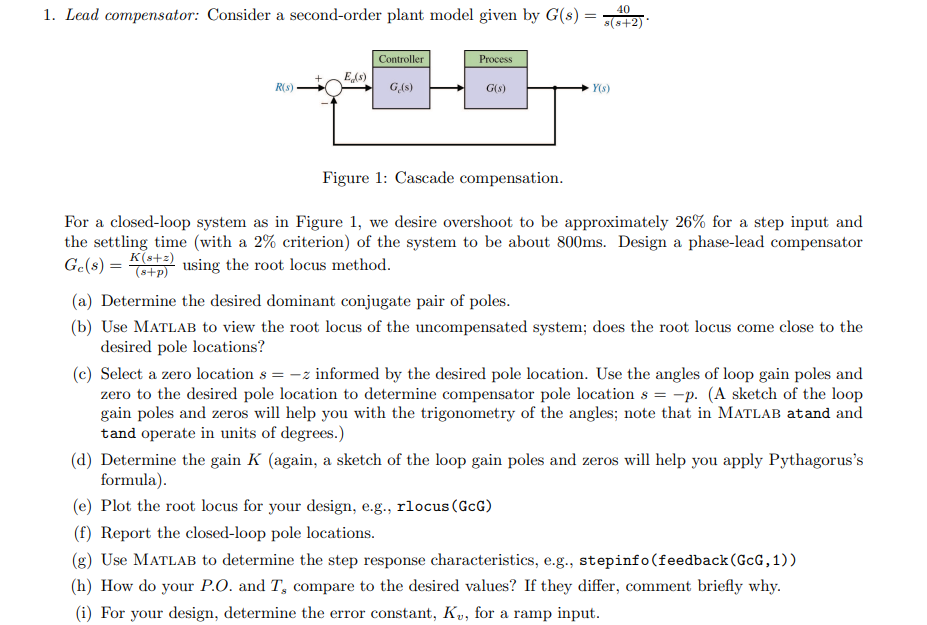
Figure : Cascade compensation.
For a closedloop system as in Figure we desire overshoot to be approximately for a step input and the settling time with a criterion of the system to be about ms Design a phaselead compensator GcsfracKszsp using the root locus method.
a Determine the desired dominant conjugate pair of poles.
b Use Matlab to view the root locus of the uncompensated system; does the root locus come close to the desired pole locations?
c Select a zero location sz informed by the desired pole location. Use the angles of loop gain poles and zero to the desired pole location to determine compensator pole location sp A sketch of the loop gain poles and zeros will help you with the trigonometry of the angles; note that in Matlab atand and tand operate in units of degrees.
d Determine the gain K again a sketch of the loop gain poles and zeros will help you apply Pythagorus's formula
e Plot the root locus for your design, eg rlocus GcG
f Report the closedloop pole locations.
g Use Matlab to determine the step response characteristics, eg stepinfofeedbackGcG
h How do your PO and Ts compare to the desired values? If they differ, comment briefly why.
i For your design, determine the error constant, Kv for a ramp input.
Step by Step Solution
There are 3 Steps involved in it
1 Expert Approved Answer
Step: 1 Unlock

Question Has Been Solved by an Expert!
Get step-by-step solutions from verified subject matter experts
Step: 2 Unlock
Step: 3 Unlock