

Question: You are to design a digitally programmable low-pass or bandpass anti-aliasing filter (AAF). The continuous-time filter runs off of dual power supplies of +/-
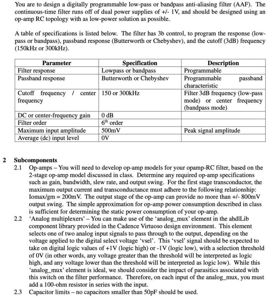
You are to design a digitally programmable low-pass or bandpass anti-aliasing filter (AAF). The continuous-time filter runs off of dual power supplies of +/- 1V, and should be designed using an op-amp RC topology with as low-power solution as possible. A table of specifications is listed below. The filter has 3b control, to program the response (low- pass or bandpass), passband response (Butterworth or Chebyshev), and the cutoff (3dB) frequency (150kHz or 300kHz). Description Programmable Programmable characteristic Parameter Filter response Passband response Specification Lowpass or bandpass Butterworth or Chebyshev passband Cutoff frequency / frequency Filter 3dB frequency (low-pass mode) or center frequency (bandpass mode) center 150 or 300kHz DC or center-frequency gain Filter order O dB 6th order Maximum input amplitude Average (dc) input level 500mV Peak signal amplitude OV 2 Subcomponents 2.1 Op-amps - You will need to develop op-amp models for your opamp-RC filter, based on the 2-stage op-amp model discussed in class. Determine any required op-amp specifications such as gain, bandwidth, slew rate, and output swing. For the first stage transconductor, the maximum output current and transconductance must adhere to the following relationship: Iomax/gm 200m V. The output stage of the op-amp can provide no more than +/- 800mV output swing. The simple approximation for op-amp power consumption described in class is sufficient for determining the static power consumption of your op-amp. 2.2 'Analog multiplexers'- You can make use of the 'analog_mux' element in the ahdlLib component library provided in the Cadence Virtuoso design environment. This element selects one of two analog input signals to pass through to the output, depending on the voltage applied to the digital select voltage 'vsel'. This 'vsel' signal should be expected to take on digital logic values of +1V (logic high) or -1V (logic low), with a selection threshold of 0V (in other words, any voltage greater than the threshold will be interpreted as logic high, and any voltage lower than the threshold will be interpreted as logic low). While this 'analog_mux' element is ideal, we should consider the impact of parasitics associated with this switch on the filter performance. Therefore, on each input of the analog_mux, you must add a 100-ohm resistor in series with the input. 2.3 Capacitor limits no capacitors smaller than 50PF should be used.
Step by Step Solution
3.38 Rating (148 Votes )
There are 3 Steps involved in it

Get step-by-step solutions from verified subject matter experts