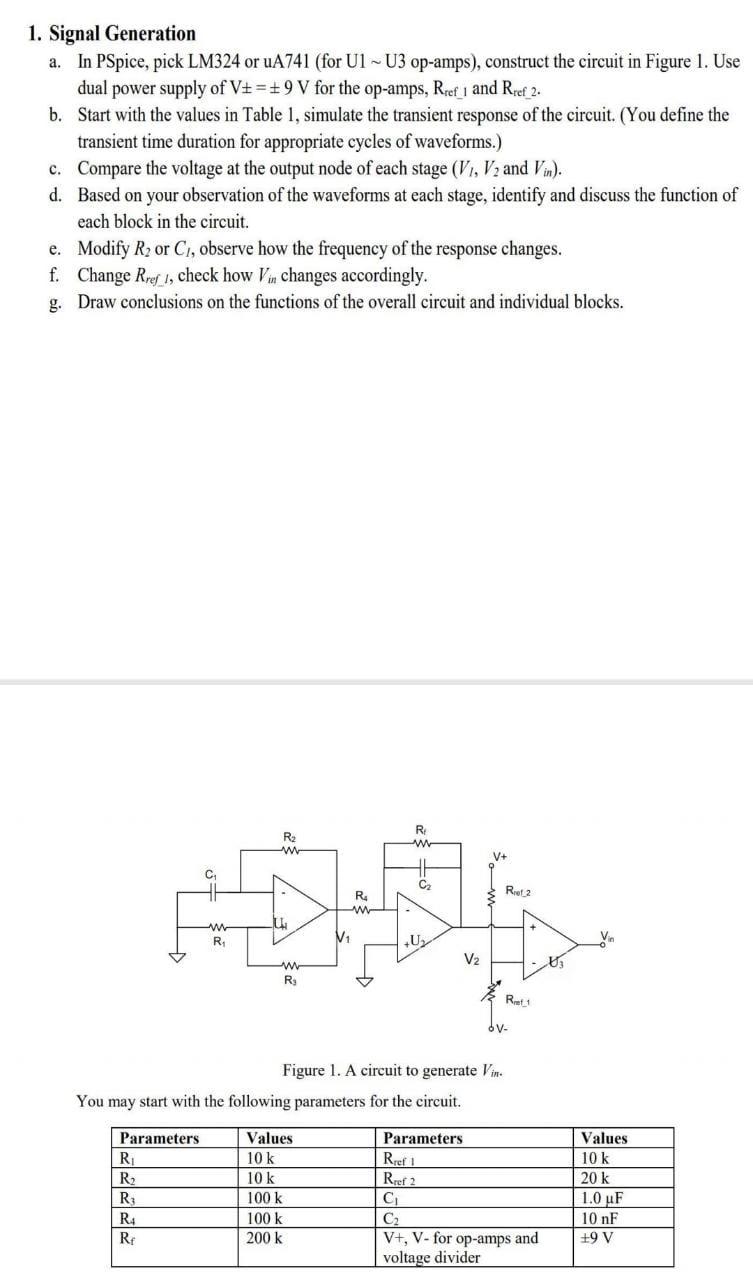
1. Signal Generation a. In PSpice, pick LM324 or uA741 (for U1 ~ U3 op-amps), construct...
Fantastic news! We've Found the answer you've been seeking!
Question:
Transcribed Image Text:
1. Signal Generation a. In PSpice, pick LM324 or uA741 (for U1 ~ U3 op-amps), construct the circuit in Figure 1. Use dual power supply of V±= ±9 V for the op-amps, Rref 1 and Rref_2. b. Start with the values in Table 1, simulate the transient response of the circuit. (You define the transient time duration for appropriate cycles of waveforms.) c. d. Compare the voltage at the output node of each stage (V₁, V₂ and Vin). Based on your observation of the waveforms at each stage, identify and discuss the function of each block in the circuit. e. Modify R₂ or C₁, observe how the frequency of the response changes. f. Change Rref 1, check how Vin changes accordingly. g. Draw conclusions on the functions of the overall circuit and individual blocks. Parameters R₁ R₂ R₁ www R₁ R4 Re R₂ www IL www R₂ R₂ www Values 10 k 10 k 100 k V₁ You may start with the following parameters for the circuit. 100 k 200 k R www C₂ U₂ Figure 1. A circuit to generate Vin V₂ Ref 2 R1 6V- Parameters Rref 1 Rref 2 C₁ C₂ V+, V- for op-amps and voltage divider Values 10 k 20 k 1.0 uF 10 nF +9 V 2. Power Driving Circuit 1) Single transistor driver a. Connect the circuit in Figure 1 to the single MOSFET in Fig. 2. Choose IRF150 for the NMOSFET. Set R = 10 kn, RLoad = 10 2. You may include a LED as part of RLoad to visualize the effect. b. Repeat the transient simulation in last section. Observe the voltage across the load resistor RLoad (i.e. V+ - VLoad) and the current passing it. Derive the power consumption by RLoad. Find the relation of the power consumption and the duty cycle of vin. d. If RLoad is a DC motor, what will be changed with a vin in Fig. 1 that has a changing duty cycle? Comment on the connection and the result. C. e. V. RLoad - V Load + Vin RS Figure 2. Powering load using a single N-MOSFET. 2) H-Bridge driver a. Construct the circuit in Figure 3. Set Vpp =9 V. In PSpice Student, use IRF150 for NMOSFETs (M_N1-3) and IRF9140 for PMOSFETs (M_P1-3). You may choose R = 10 k2. b. Set Vin as 9 V and 0 V, respectively, check the voltage across R₁, i.e., Vo 2- Vo 1. Identify the direction of current passing RL. (You may use a pulse voltage source as Vin.) Connect the two circuits (Figure 1 and Figure 3) together. Perform transient analysis as done in Section 1. Check the current passing R₁. (Due to the nodes limit in PSpice_Student, you may need to use LTSpice for this complete simulation.) e. d. Change the value of R₂ or C₁, observe how it affects Vo_1, Vo_2 and the current passing R₁. With certain R2 and C1, change Rref 1, observe how Vo 1,Vo 2 and IRL change accordingly. Record the waveforms (VL Vo2 - Vo 1 and IRL) of two settings of Rref 1. Calculate the power dissipated by RL. C. Vo 1 R M_P3 HE M_N2 M_N3 Vin 14 9 Voo M_P1 RL www M_P2 Vo_2 오 M_N1 T R Figure 3. A generic H-bridge circuit. The inverter consisted of M_P3 and M_N3 can be small signal transistors such as those in a CD4007 chip that was used in previous labs. Other MOSFETs should be power transistors. 1. Signal Generation a. In PSpice, pick LM324 or uA741 (for U1 ~ U3 op-amps), construct the circuit in Figure 1. Use dual power supply of V±= ±9 V for the op-amps, Rref 1 and Rref_2. b. Start with the values in Table 1, simulate the transient response of the circuit. (You define the transient time duration for appropriate cycles of waveforms.) c. d. Compare the voltage at the output node of each stage (V₁, V₂ and Vin). Based on your observation of the waveforms at each stage, identify and discuss the function of each block in the circuit. e. Modify R₂ or C₁, observe how the frequency of the response changes. f. Change Rref 1, check how Vin changes accordingly. g. Draw conclusions on the functions of the overall circuit and individual blocks. Parameters R₁ R₂ R₁ www R₁ R4 Re R₂ www IL www R₂ R₂ www Values 10 k 10 k 100 k V₁ You may start with the following parameters for the circuit. 100 k 200 k R www C₂ U₂ Figure 1. A circuit to generate Vin V₂ Ref 2 R1 6V- Parameters Rref 1 Rref 2 C₁ C₂ V+, V- for op-amps and voltage divider Values 10 k 20 k 1.0 uF 10 nF +9 V 2. Power Driving Circuit 1) Single transistor driver a. Connect the circuit in Figure 1 to the single MOSFET in Fig. 2. Choose IRF150 for the NMOSFET. Set R = 10 kn, RLoad = 10 2. You may include a LED as part of RLoad to visualize the effect. b. Repeat the transient simulation in last section. Observe the voltage across the load resistor RLoad (i.e. V+ - VLoad) and the current passing it. Derive the power consumption by RLoad. Find the relation of the power consumption and the duty cycle of vin. d. If RLoad is a DC motor, what will be changed with a vin in Fig. 1 that has a changing duty cycle? Comment on the connection and the result. C. e. V. RLoad - V Load + Vin RS Figure 2. Powering load using a single N-MOSFET. 2) H-Bridge driver a. Construct the circuit in Figure 3. Set Vpp =9 V. In PSpice Student, use IRF150 for NMOSFETs (M_N1-3) and IRF9140 for PMOSFETs (M_P1-3). You may choose R = 10 k2. b. Set Vin as 9 V and 0 V, respectively, check the voltage across R₁, i.e., Vo 2- Vo 1. Identify the direction of current passing RL. (You may use a pulse voltage source as Vin.) Connect the two circuits (Figure 1 and Figure 3) together. Perform transient analysis as done in Section 1. Check the current passing R₁. (Due to the nodes limit in PSpice_Student, you may need to use LTSpice for this complete simulation.) e. d. Change the value of R₂ or C₁, observe how it affects Vo_1, Vo_2 and the current passing R₁. With certain R2 and C1, change Rref 1, observe how Vo 1,Vo 2 and IRL change accordingly. Record the waveforms (VL Vo2 - Vo 1 and IRL) of two settings of Rref 1. Calculate the power dissipated by RL. C. Vo 1 R M_P3 HE M_N2 M_N3 Vin 14 9 Voo M_P1 RL www M_P2 Vo_2 오 M_N1 T R Figure 3. A generic H-bridge circuit. The inverter consisted of M_P3 and M_N3 can be small signal transistors such as those in a CD4007 chip that was used in previous labs. Other MOSFETs should be power transistors.
Expert Answer:
Answer rating: 100% (QA)
1 Signal Generation a In PSpice construct the circuit in Figure 1 using LM324 or uA741 opamps U1U3 w... View the full answer
Related Book For
Posted Date:
Students also viewed these accounting questions
-
Based on your observation and experience, draw a motion diagram showing the position, velocity, and acceleration vectors for a pendulum that swings in an arc carrying from an initial position 45 to...
-
Prepare a reflective analysis based on your observation and its links with consumer behaviour theories covered in weeks 1 to 4. Refection requires you to observe, describe and make meaning of...
-
Blocks D and F weigh W1 each and block E weighs W2. Determine the sag s for equilibrium. Neglect the size of the pulleys. Given: W1 = 5 lb W2 = 8 lb a = 4 ft E F
-
Custom Truck Builders frequently uses long-term lease contracts to finance the sale of its trucks. On November 1, 2015, Custom Truck Builders leased to Interstate Van Lines a truck carried in the...
-
What is the purpose of the raw materials subsidiary ledger? How is it related to the general ledger?
-
Prove that the boosted right-handed spinor \(\psi_{\mathrm{R}}(\boldsymbol{p})\) is related to the corresponding rest spinor by Eq. (14.21).
-
The Wide World of Fluids article titled "Motorized Surfboard,". The thrust to propel the powered surfboard shown in Fig. P5.76 is a result of water pumped through the board that exits as a high-speed...
-
DeColores Paint Company owns ten trucks that it uses to deliver paint and decorating supplies to builders. On average, each truck returns to the companys single loading dock at a rate of three times...
-
How did we get 9.38% and why are we using this for cost of capital. Is there a calculation or formula? Why are we using this as the discount rate? WACC = 9.38% for the target D/V of 20.99
-
LaneScapes Incorporated Transactions Background LaneScapes Incorporated is a newly founded corporation in Oregon that provides premium ecologically conscious landscaping services in Lane County....
-
The induced magnetic field at radial distance 8.1 mm from the central axis of a circular parallel-plate capacitor is 2.2 x 10⁶ T. The plates have radius 4.1 mm. At what rate is the magnitude of the...
-
1. A 220 ml concentrated hydrochloric acid solution is 26,42% HCI and 73.58% water by mass. The specific gravity of the solution is 1.165. a. What mass of pure HCI is contained in this solution? b....
-
Through the COVID-19 pandemic, we have all learned the phrase "the new normal." This pandemic has required all of us to become highly adaptive and agile in the way we navigate our personal and...
-
Explain why some people may speak or act in ways that could be considered a microaggression .
-
Given the following information, complete the first stage of allocation for the ABC method. Do NOT use dollar signs ($). Cost Pool Description Estimated Cost Driver and guard wages $720,000 Vehicle...
-
Clara is making her grocery shopping list through her store's mobile app. She needs pasta sauce, so she adds Prego to the list since it is the brand she always buys. Later that morning while checking...
-
The Hertz solution for u is: u_(r) = 2D 00 Pl mJ (mr/1) 4 1+ m m=0 dm The solution for u. due to a load spread over a circle with radius a is: u_(r) = P m=0 Jo(mr/1)J (ma/1) 1+ m 4 -dm (wherein J,...
-
If you want to solve a minimization problem by applying the geometric method to the dual problem, how many variables and problem constraints must be in the original problem?
-
A single link of a robot arm is shown in Figure. The arm mass is m and its center of mass is located a distance L from the joint, which is driven by a motor torque Tm through two pairs of spur gears....
-
Refer to Figure 7.1.4a, and suppose that p1 - p2 = 10 lb/in.2, A = 3 in.2, and mg = 600 lb. If the mass starts from rest at x(0) = 0, how far will it move in 0.5 sec, and how much hydraulic fluid...
-
Suppose a mass m moving with a speed v1 becomes embedded in mass m2 after striking it (Figure 4.6.1). Suppose m2 = 5m. Determine the expression for the displacement x(t) after the collision.
-
How can we effectively analyze a firm's financial ratios?
-
BlackBerry Ltd. has a target current ratio of 2.0 but has experienced some difficulties financing its expanding sales in the past few months. At present, the firm has current assets of $750,000 and a...
-
Cheung Keong Ltd. currently has \($2,150,000\) in current assets and \($860,000\) in current liabilities. The companys managers want to increase the firms inventory, which will be financed by a...
Study smarter with the SolutionInn App