

Question: 1 . The D Flip - Flop a ) Look for the datasheet of the 7 4 7 4 D flip - flop and wire
The D FlipFlop
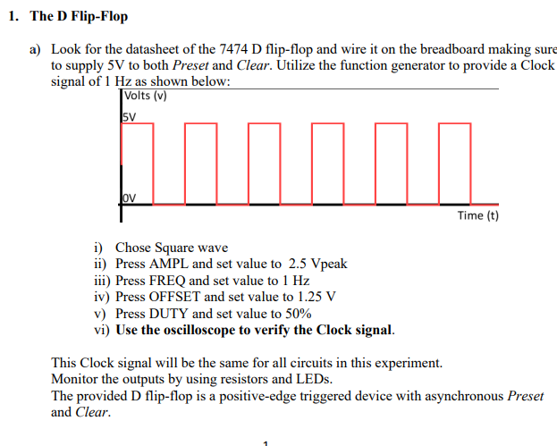
a Look for the datasheet of the D flipflop and wire it on the breadboard making sure to supply V to both Preset and Clear. Utilize the function generator to provide a Clock signal of Hz as shown below:
i Chose Square wave
ii Press AMPL and set value to Vpeak
iii Press FREQ and set value to Hz
iv Press OFFSET and set value to V
v Press DUTY and set value to
vi Use the oscilloscope to verify the Clock signal.
This Clock signal will be the same for all circuits in this experiment.
Monitor the outputs by using resistors and LEDs.
The provided D flipflop is a positiveedge triggered device with asynchronous Preset and Clear. b How does the output Q behave in response to input D
c With the information gathered from step b fill out the characteristic table corresponding to a D flipflop.
d Change input Preset to LOW and record the outcome. mathrmQ Change input Preset back to HIGH.
e Change input Clear to LOW and record the outcome. mathrmQ Change input Clear back to HIGH.
f With the information gathered from steps a through e above, complete the following timing diagram.
Step by Step Solution
There are 3 Steps involved in it
1 Expert Approved Answer
Step: 1 Unlock

Question Has Been Solved by an Expert!
Get step-by-step solutions from verified subject matter experts
Step: 2 Unlock
Step: 3 Unlock