

Question: 1 . The shaft shown in Figure ( 4 - 7 ) is supported by two bearings and carries two V - belt
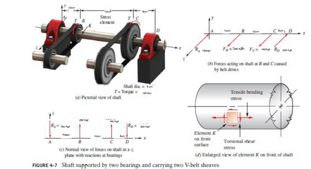
The shaft shown in Figure is supported by two bearings and carries two Vbelt sheaves. The tensions in the belts exert horizontal forces on the shaft, tending to bend it in the xz plane. Sheave B exerts a clockwise torque on the shaft when viewed toward the origin of the coordinate system along the x axis. Sheave C exerts an equal but opposite torque on the shaft. For the loading condition shown, determine the principal stresses and the maximum shear stress on element K on the front surface of the shaft on the positive z side just to the right of sheave B points
Follow the general procedure for analyzing combined stresses given in this section.
Use the procedure for constructing the D Mohr's circle in this section.
Can you extend this example to cover Tresca Tresca Stress and von Mises Stress?
Where,
A B and B C mathrm~cm and C D mathrm~cm
Shaft Diameter cm
Torque Nm
Ra Kgd
Rb Kgf
Rc Kgf
Rd Kgf plane with reactions at bearings
Step by Step Solution
There are 3 Steps involved in it
1 Expert Approved Answer
Step: 1 Unlock

Question Has Been Solved by an Expert!
Get step-by-step solutions from verified subject matter experts
Step: 2 Unlock
Step: 3 Unlock