

Question: The shaft shown in the figure is supported by two bearings and carries two V-belt sheaves. The tensions in the belts exert horizontal forces
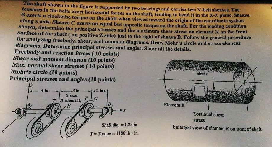
The shaft shown in the figure is supported by two bearings and carries two V-belt sheaves. The tensions in the belts exert horizontal forces on the shaft, tending to bend it in the X-Z plane. Sheave B exerts a clockwise torque on the shaft when viewed toward the origin of the coordinate system along x axis. Sheave C exerts an equal but opposite torque on the shaft, For the loading condition shown, determine the principal stresses and the maximum shear stress on element K on the front surface of the shaft ( on positive Z side) just to the right of sheave B. Follow the general procedure for analyzing freebody, shear, and moment diagrams. Draw Mohr's circle and stress element diagrams. Determine principal stresses and angles. Show all the details. Freebody and reaction forces ( 10 points) Shear and moment diagram (10 points) Max. normal shear stresses ( 10 points) Mohr's circle (10 points) Principal stresses and angles (10 points) stress 4 in- 4 in- Stress r'B element, Element K Torsional shear stress Shaft dia, = 1.25 in Enlarged view of element K on front of shaft T= Torque = 1100 lb in
Step by Step Solution
3.53 Rating (163 Votes )
There are 3 Steps involved in it
4 in hin Gata Titi 2 1 Ta TI TI uo Torque T 1000 lbin shaft diameter d 125 in TGTD maxt... View full answer

Get step-by-step solutions from verified subject matter experts