

Question: 1. This problem concerns the design of a digital system which multiplies two binary numbers by the re- peated addition method. The block diagram of
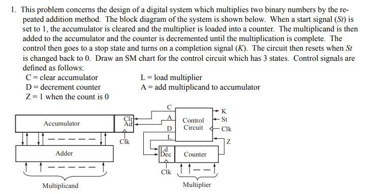
1. This problem concerns the design of a digital system which multiplies two binary numbers by the re- peated addition method. The block diagram of the system is shown below. When a start signal (St) is set to 1, the accumulator is cleared and the multiplier is loaded into a counter. The multiplicand is then added to the accumulator and the counter is decremented until the multiplication is complete. The control then goes to a stop state and turns on a completion signal (K). The circuit then resets when St is changed back to 0. Draw an SM chart for the control circuit which has 3 states. Control signals are defined as follows: C=clear accumulator L = load multiplier D = decrement counter A = add multiplicand to accumulator Z= 1 when the count is 0 K Accumulator Cl; Ad Control Circuit St Cik D L Cik Z Adder Ld Dec Counter Clk 11--1 Multiplicand Multiplier 1. This problem concerns the design of a digital system which multiplies two binary numbers by the re- peated addition method. The block diagram of the system is shown below. When a start signal (St) is set to 1, the accumulator is cleared and the multiplier is loaded into a counter. The multiplicand is then added to the accumulator and the counter is decremented until the multiplication is complete. The control then goes to a stop state and turns on a completion signal (K). The circuit then resets when St is changed back to 0. Draw an SM chart for the control circuit which has 3 states. Control signals are defined as follows: C=clear accumulator L = load multiplier D = decrement counter A = add multiplicand to accumulator Z= 1 when the count is 0 K Accumulator Cl; Ad Control Circuit St Cik D L Cik Z Adder Ld Dec Counter Clk 11--1 Multiplicand Multiplier
Step by Step Solution
There are 3 Steps involved in it

Get step-by-step solutions from verified subject matter experts