

Question: 1 , USING THE PLAN PROVIDED TO FIX THE STRAIGHTS The plan was originally drawn at a scale of 1 : 2 , 0 0
USING THE PLAN PROVIDED TO FIX THE STRAIGHTS
The plan was originally drawn at a scale of : but after scanning and printing it may not now be at that scale.
You must find the scale of your plan.
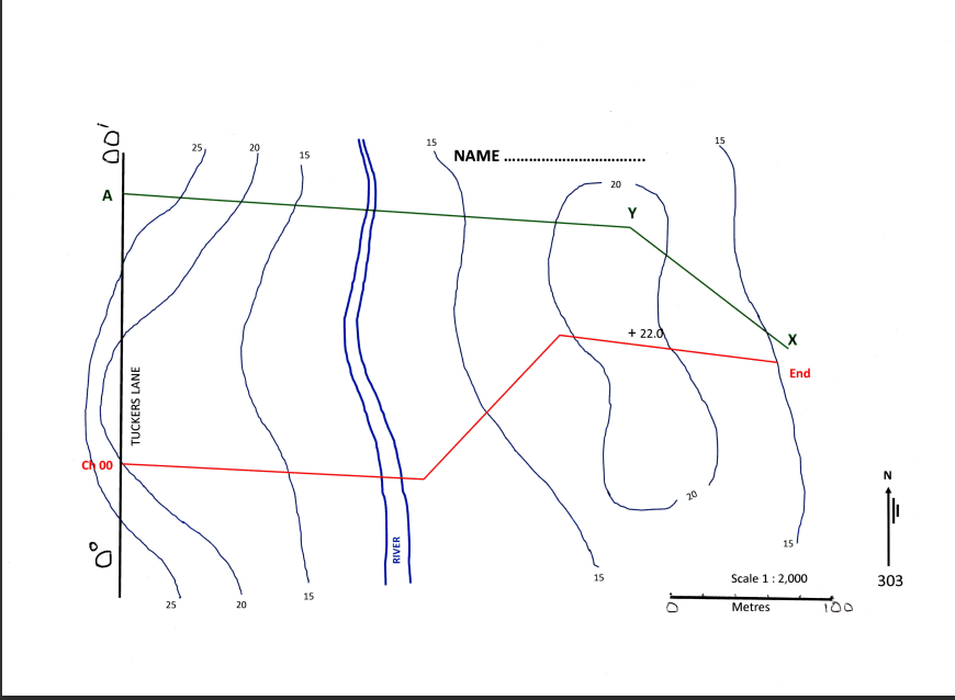
As well as the bar scale showing m there are three surveyed lines, for which precise horizontal distances are known and are shown on the next page. Measure each of the four lines in mm and show these measurements in your answer sheet. Using the given true horizontal distances, compute the scale of your plan and state this in the answer sheet.
The plan provided has a contour interval of m Assume that the contours are correct with confidence.
Using your plan, by scale, find the bearings and distances of each of the three straights. Quote your answers to the nearest metre and nearest degree and adopt these values as being fixed for each straight. ie each straight will be exactly an even metre long and have a bearing precise to one degree only.
Use Tuckers Lane as your azimuth
CHAINAGES FOR THE HORIZONTAL ALIGMENT OF THE ROAD
Determine the deflection angle at each I.P
Each horizontal curve is to have radius of m
Calculate the tangent distance and arc length for each curve to decimal places and show them in the table of answers
Calculate the chainages of each of the four horizontal curve TPs and the end of the road, and any other points listed, and show them all in the table of answersYou will need to use these values in the rest of your design; eg for the end of the road and the TPs
On your plan, mark the bearing and distance of each straight. Also, plot each TP and then draw in the horizontal curve. Freehand is acceptable. If you calculate the external distance, you will have a third point to help you draw the curve. Then neatly write in the chainages of each TP and the end of your road.
The plan must be attached to your answer.
VERTICAL ALIGNMENT
Using the information shown on your contour map, draw a longsection of the Centre Line of your road at scales; horizontal : and vertical :Please read the submission section for detailed guidance about drawing the longsection.
Scale the distances along the road to each contour and show the results on the table of your answer sheet.
Design a vertical alignment of the centre line of the road showing grades and vertical
curves. The vertical alignment must meet the following criteria:
The road must start at RL It must finish exactly at RL at the chainage you have calculated as being the end of the road.
The Natural Surface RL at the start of the road is and at the end of the road is exactly the same as the finishing Design RL of the road.
The first IP of the vertical design must lie at Chainage and RL After that you must complete the vertical design using two or three at most rising grades and one falling grade, which generally follow the land surface. You must aim to keep the road ie the cut or fill within m of the natural surface. If this cannot be achieved in a maximum of four new grades, complete your design using four grades and then make a brief report and explain where the road has excess cut or fill and by how much.
The grades you select for your design of the road must be between and
Vertical curves must have lengths of only mm or m The I.P of each vertical curve must be located at an even m chainage ie etc. and must not be placed at odd locations such as All grades used must be to no greater precision than except for the final grade to the end of the line. ie grades such as must be used for every grade, except the final one where additional decimal places may be shown, if necessary, to ensure that the Design RL meets the set RL
Every change of grade requires a vertical curve. Assume that your road will meet Tuckers Road precisely at the nominated RL No vertical curve will be needed at this road junction.
Complete the table with your vertical curve calculations for the design levels.
Calculate the Design Levels at every m of running chainage along the road. Also calculate the chainage to dp and RL of the low point of the road at the river crossing.
River and River Crossing Information
The banks of the river where the road crosses it are at RL
At the river crossing, the design level of the road must be between m and m above the riverbanks to allow for a culvert to be built. If you believe that this cant be achieved design the road to be as close as possible to this specification and report the difference.
TRAVERSE CALCULATIONS TO SET OUT THE END OF THE ROAD
A survey party has run an accurate EDM traverse from point X via Y to A and then connected to the start of the road Ch
The coordinates of A are m Em N
Horizontal angle xya :
distance yx: m
angle yach :
distance ay:
distance ach:
Step by Step Solution
There are 3 Steps involved in it
1 Expert Approved Answer
Step: 1 Unlock

Question Has Been Solved by an Expert!
Get step-by-step solutions from verified subject matter experts
Step: 2 Unlock
Step: 3 Unlock