

Question: 10. [1.5 pts] {Section C} a. Draw a ray diagram of the lens system as it should look at the end of Step C6
![10. [1.5 pts] {Section C} a. Draw a ray diagram of the](https://dsd5zvtm8ll6.cloudfront.net/si.experts.images/questions/2022/12/6393d0e247414_6506393d0e21d13d.jpg)
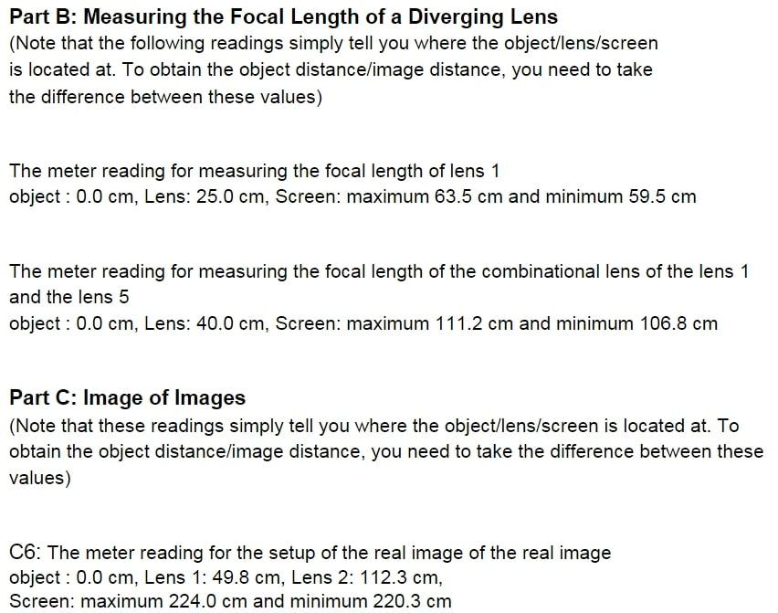
10. [1.5 pts] {Section C} a. Draw a ray diagram of the lens system as it should look at the end of Step C6 (the setup for forming the image of a real image). Draw the ray diagram roughly to scale and label all lengths (based on the values given in the dataset.) b. Describe in one sentence the final image as accurately as possible (characterize its type and its appearance relative to the original object). Part B: Measuring the Focal Length of a Diverging Lens (Note that the following readings simply tell you where the object/lens/screen is located at. To obtain the object distance/image distance, you need to take the difference between these values) The meter reading for measuring the focal length of lens 1 object : 0.0 cm, Lens: 25.0 cm, Screen: maximum 63.5 cm and minimum 59.5 cm The meter reading for measuring the focal length of the combinational lens of the lens 1 and the lens 5 object : 0.0 cm, Lens: 40.0 cm, Screen: maximum 111.2 cm and minimum 106.8 cm Part C: Image of Images (Note that these readings simply tell you where the object/lens/screen is located at. To obtain the object distance/image distance, you need to take the difference between these values) C6: The meter reading for the setup of the real image of the real image object : 0.0 cm, Lens 1: 49.8 cm, Lens 2: 112.3 cm, Screen: maximum 224.0 cm and minimum 220.3 cm
Step by Step Solution
3.38 Rating (160 Votes )
There are 3 Steps involved in it
Answer GIVEN C6 The meter reading for the setup of the real image of the ... View full answer

Get step-by-step solutions from verified subject matter experts