

Question: (10 points) To implement the NOT instruction in LC-3, five cycles are required. Below are the operations performed in each of these cycles: cycle 1:MARPC,PCPC+1
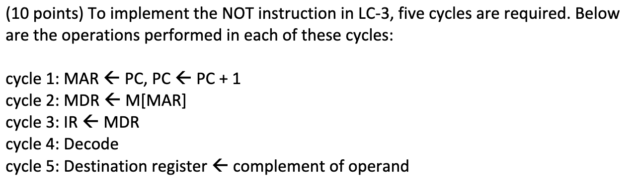
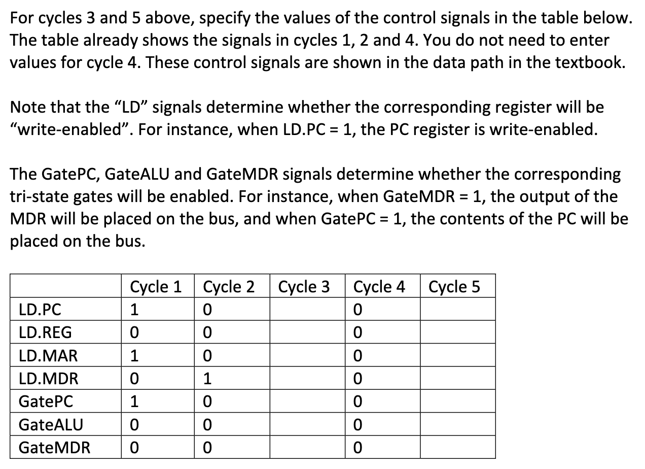
(10 points) To implement the NOT instruction in LC-3, five cycles are required. Below are the operations performed in each of these cycles: cycle 1:MARPC,PCPC+1 cycle 2:MDRM[MAR] cycle 3:IIRMDR cycle 4: Decode cycle 5: Destination register complement of operand For cycles 3 and 5 above, specify the values of the control signals in the table below. The table already shows the signals in cycles 1, 2 and 4. You do not need to enter values for cycle 4. These control signals are shown in the data path in the textbook. Note that the "LD" signals determine whether the corresponding register will be "write-enabled". For instance, when LD.PC =1, the PC register is write-enabled. The GatePC, GateALU and GateMDR signals determine whether the corresponding tri-state gates will be enabled. For instance, when GateMDR =1, the output of the MDR will be placed on the bus, and when GatePC =1, the contents of the PC will be placed on the bus
Step by Step Solution
There are 3 Steps involved in it

Get step-by-step solutions from verified subject matter experts