

Question: 16. For the program in the figure below, what is the address of the instruction associated with the pressure switch? a) I:1/0 b) I:1/2 c)
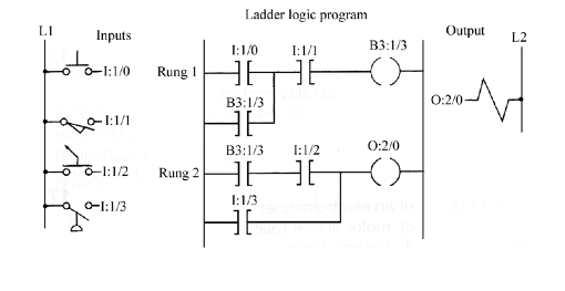
16. For the program in the figure below, what is the address of the instruction associated with the pressure switch?
a) I:1/0
b) I:1/2
c) I:1/1
d) I:1/3
17. When would O:2/0 be energized, when would it be de-energized?
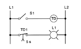
18. In the hardwired circuit of the figure shown below, the light will stay on:
a) as long as S1 is closed.
b) for 5 s after coil TD is energized.
c) for 5 s after coil TD is de-energized.
d) both a and c.
19. Which one of the following timer parameters determines the time duration for the timing circuit?
a) Accumulated time.
b) Preset time.
c) Timer address.
d) Time base.
20. Which one of the following timer parameters represents the value that increments as the timer is timing?
a) Accumulated time.
b) Preset time.
c) Timer address.
d) Time base
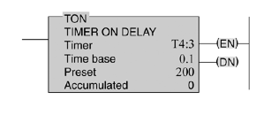
21. For the on-delay timer instruction shown in the figure below, the timer number is:
a) 0
b) 200
c) T4:3
d) 0.1
22. The on-delay timed period would be:
a) 3 seconds
b) 4 seconds
c) 20 seconds
d) 200 seconds
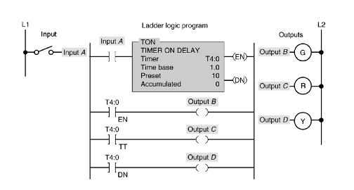
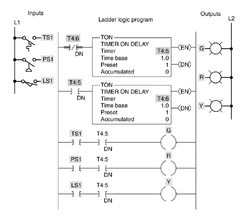
23. For the figure below indicate the on/off status of the three outputs at the following time intervals.
Switch A de-energized, T=0
Switch A energized, T=0
Switch A energized, T = 5 -
Switch A energized, T = 10 -
Switch A de-energized, T = 15 -
24. For the timer table shown in Figure 7-7, bit level addressing is used for:
a) EN, TT, PRE and ACC
b) EN, TT, and DN
c) PRE, ACC, TT and EN
d) PRE and ACC
25. Describe the operation of the program illustrated below. What occurs when PB1 is pressed at time T=0, T=15?
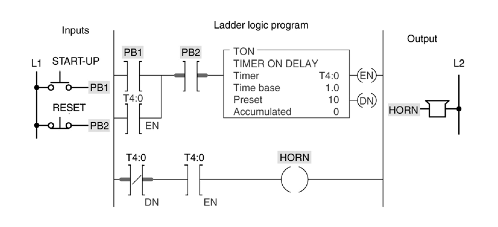
25. The off-delay timer (TOF) starts timing when the timer's:
a) ladder rung switches from false to true.
b) ladder rung switches from true to false.
c) accumulated value equals its preset value
d) accumulated is greater than its preset value
26. The main difference between a PLC retentive and nonretentive timer is that the:
a) retentive timer can be programmed for much longer time delay periods.
b) nonretentive time can be programmed for much longer time delay
periods.
c) retentive timer maintains the current time should power be removed from
the device or when the timer rung goes false.
d) nonretentive timer maintains the current time should power be removed
from the device or when the timer rung goes false.
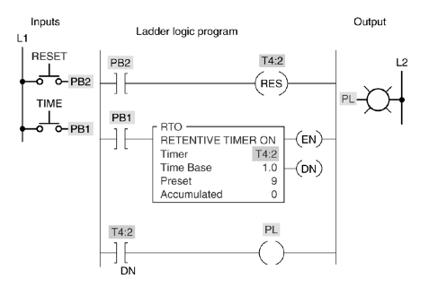
27. For the figure below if PB1 is depressed at time T=0, and then released at time T=5, then pressed again at time T = 20. What will be the status of the output PL at time T = 24?
28. Describe the operation of the output G when the input TS1 is energized.
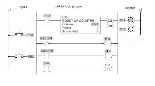
29. In the program below PB1 is depressed 10 times, and PB2 is pressed once. What is the status of the tow outputs PL1 and PL2?
Ladder logic program LI L.1 Inputs Output L2 B3:1/3 0-1:10 Rung 1 B3:13 O:2/0 O:2/0 B3:1/3 1:12 -1:/2 Rung 2 I:13
Step by Step Solution
There are 3 Steps involved in it

Get step-by-step solutions from verified subject matter experts