

Question: 1.your task is :-The project needs to be completed using Logisim software. please submit the logisim file (.circ) please don't submit any other answers that
1.your task is :-The project needs to be completed using Logisim software. please submit the logisim file (.circ)
please don't submit any other answers that exist in chegg already.
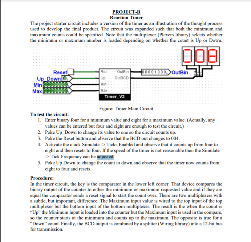
PROJECT-B Reaction Timer The project starter circuit includes a version of the timer as an illustration of the thought process used to develop the final product. The circuit was expanded such that both the minimum and maximum counts could be specified. Note that the multiplexer (Plexers library) selects whether the minimum or maximum number is loaded depending on whether the count is Up or Down. 09 00001000, OutBin Reset! Up Down O. Min 00000000 Max 00000000 Rst OutBin Up OutBCD Min Max Timer_v3 Figure: Timer Main Circuit To test the circuit: 1. Enter binary four for a minimum value and eight for a maximum value. (Actually, any values can be entered but four and eight are enough to test the circuit.) 2. Poke Up Down to change its value to one so the circuit counts up. 3. Poke the Reset button and observe that the BCD out changes to 004. 4. Activate the clock Simulate -> Ticks Enabled and observe that it counts up from four to eight and then resets to four. If the speed of the timer is not reasonable then the Simulate -> Tiek Frequency can be adjusted. 5. Poke Up Down to change the count to down and observe that the timer now counts from eight to four and resets. Procedure: In the timer circuit, the key is the comparator in the lower left corner. That device compares the binary output of the counter to either the minimum or maximum requested value and if they are equal the comparator sends a reset signal to start the count over. There are two multiplexers with a subtle, but important, difference. The Maximum input value is wired to the top input of the top multiplexer but the bottom input of the bottom multiplexer. The result is the when the count is "Up" the Minimum input is loaded into the counter but the Maximum input is used in the compare, so the counter starts at the minimum and counts up to the maximum. The opposite is true for a "Down count. Finally, the BCD output is combined by a splitter (Wiring library) into a 12-bit bus for transmission
Step by Step Solution
There are 3 Steps involved in it

Get step-by-step solutions from verified subject matter experts