

Question: 2 . 1 Given: The framing diagram shown below. Assume a 1 0 0 psf gravity load ( includes both dead and live load )
Given:
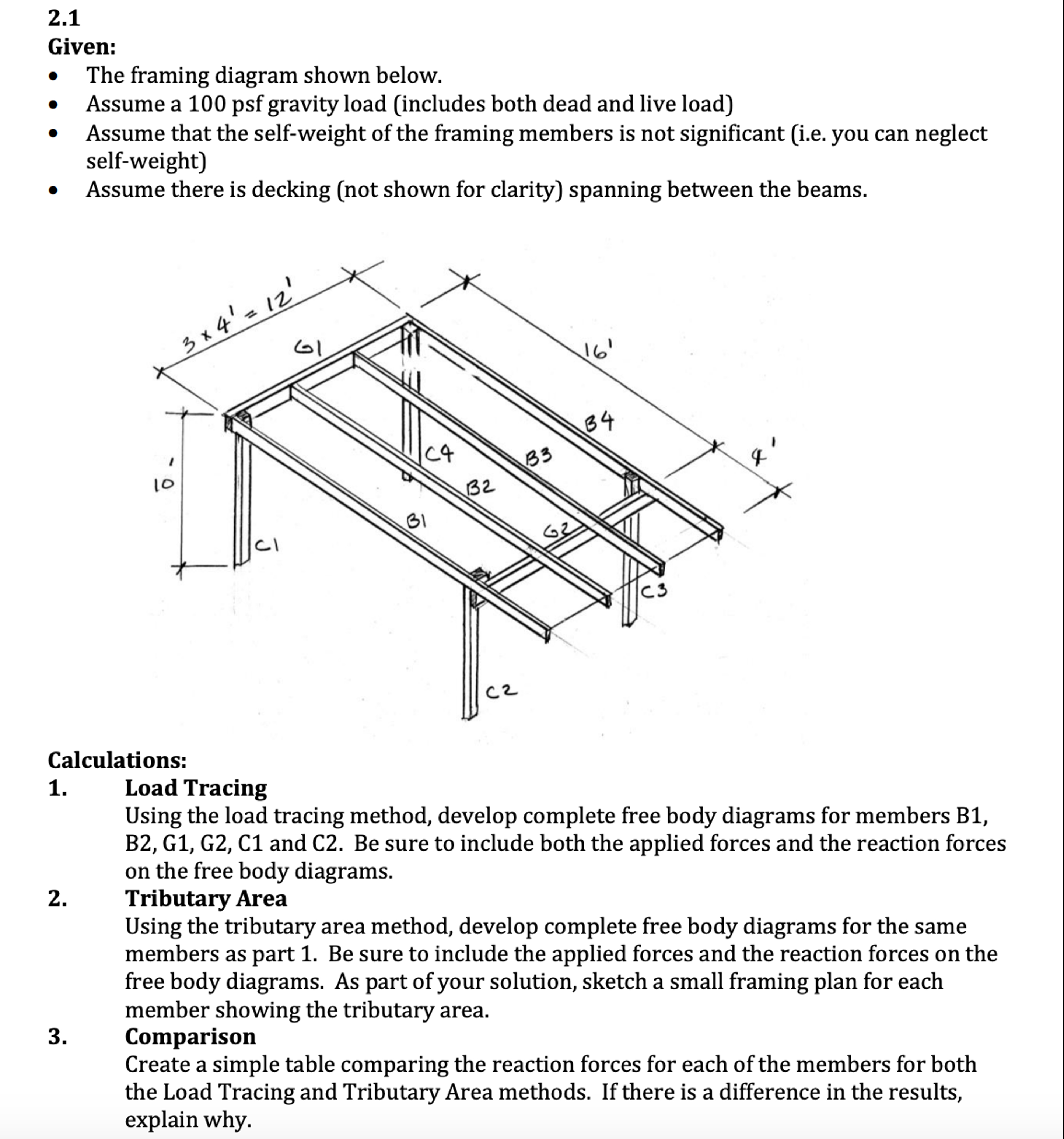
The framing diagram shown below.
Assume a psf gravity load includes both dead and live load
Assume that the selfweight of the framing members is not significant ie you can neglect
selfweight
Assume there is decking not shown for clarity spanning between the beams.
Calculations:
Load Tracing
Using the load tracing method, develop complete free body diagrams for members B
B G G C and C Be sure to include both the applied forces and the reaction forces
on the free body diagrams.
Tributary Area
Using the tributary area method, develop complete free body diagrams for the same
members as part Be sure to include the applied forces and the reaction forces on the
free body diagrams. As part of your solution, sketch a small framing plan for each
member showing the tributary area.
Comparison
Create a simple table comparing the reaction forces for each of the members for both
the Load Tracing and Tributary Area methods. If there is a difference in the results,
explain why.
Step by Step Solution
There are 3 Steps involved in it
1 Expert Approved Answer
Step: 1 Unlock

Question Has Been Solved by an Expert!
Get step-by-step solutions from verified subject matter experts
Step: 2 Unlock
Step: 3 Unlock