

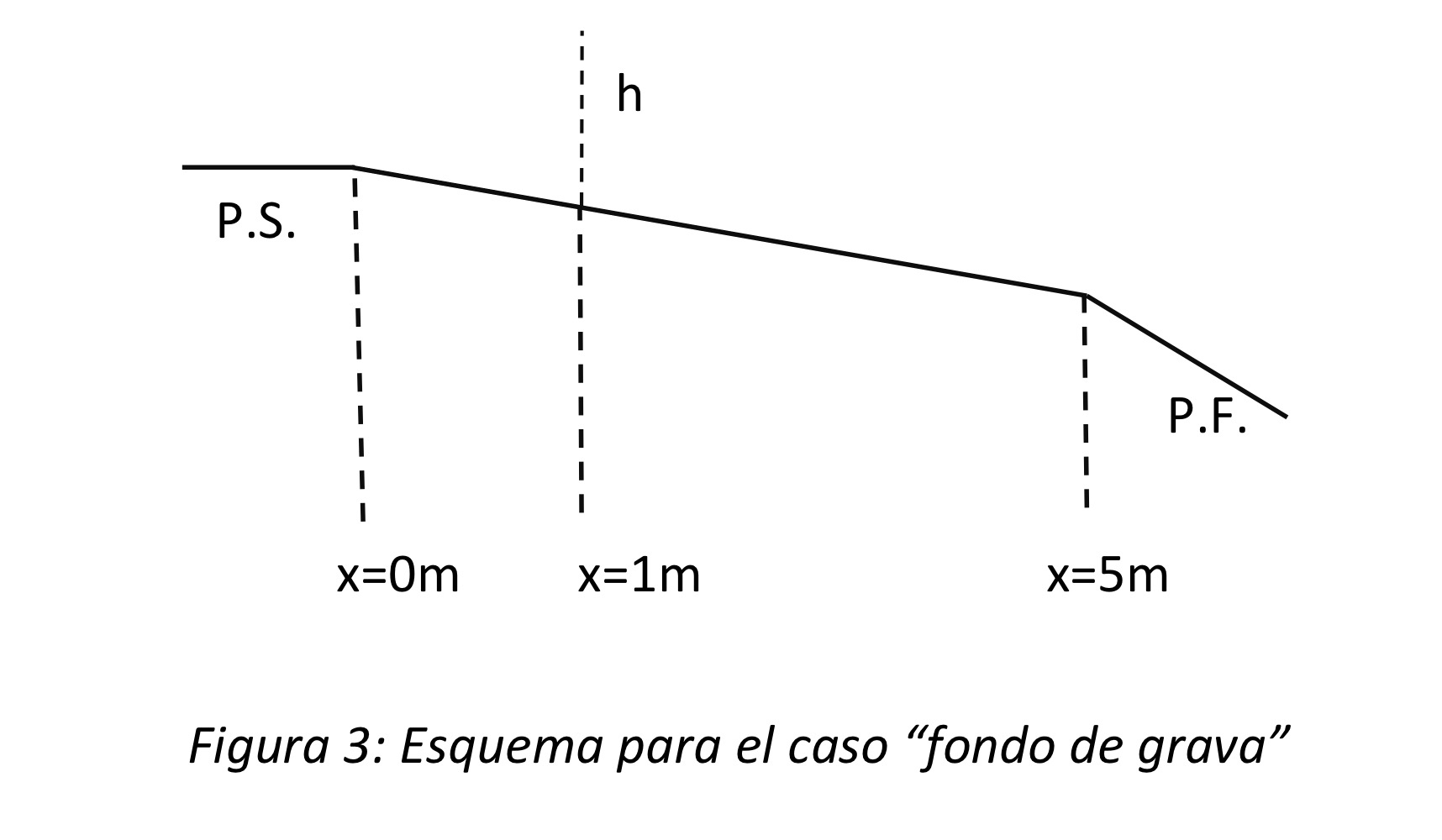
Question: 2 . 2 Case 2 : Gravel bottom Figure 3 shows a schematic of the case and the distances to be used. Figure 3 :
Case : Gravel bottom Figure shows a schematic of the case and the distances to be used. Figure : Schematic for the "gravel bottom" case. Data: Channel width: bm Channel slope: i Flow rate Qls Roughness n Develop: Calculate the critical head. Calculate the normal head. Classify the runoff profile. Determine a control point. At the point xm calculate the runoff head using the method of Calculate the normal head. Calculate the calculated distance from the depth Plot the runoff head as a function of distance x along the length of the channel. channel. Comment, including data, on what happens to the hydraulic slope as the channel roughness changes using method change the chann roughness gravel bottom and steel bottom
Step by Step Solution
There are 3 Steps involved in it
1 Expert Approved Answer
Step: 1 Unlock

Question Has Been Solved by an Expert!
Get step-by-step solutions from verified subject matter experts
Step: 2 Unlock
Step: 3 Unlock