

Question: * 2 . 7 8 The two circuits in Fig. P 2 . 7 8 are intended to function as voltage - to - current
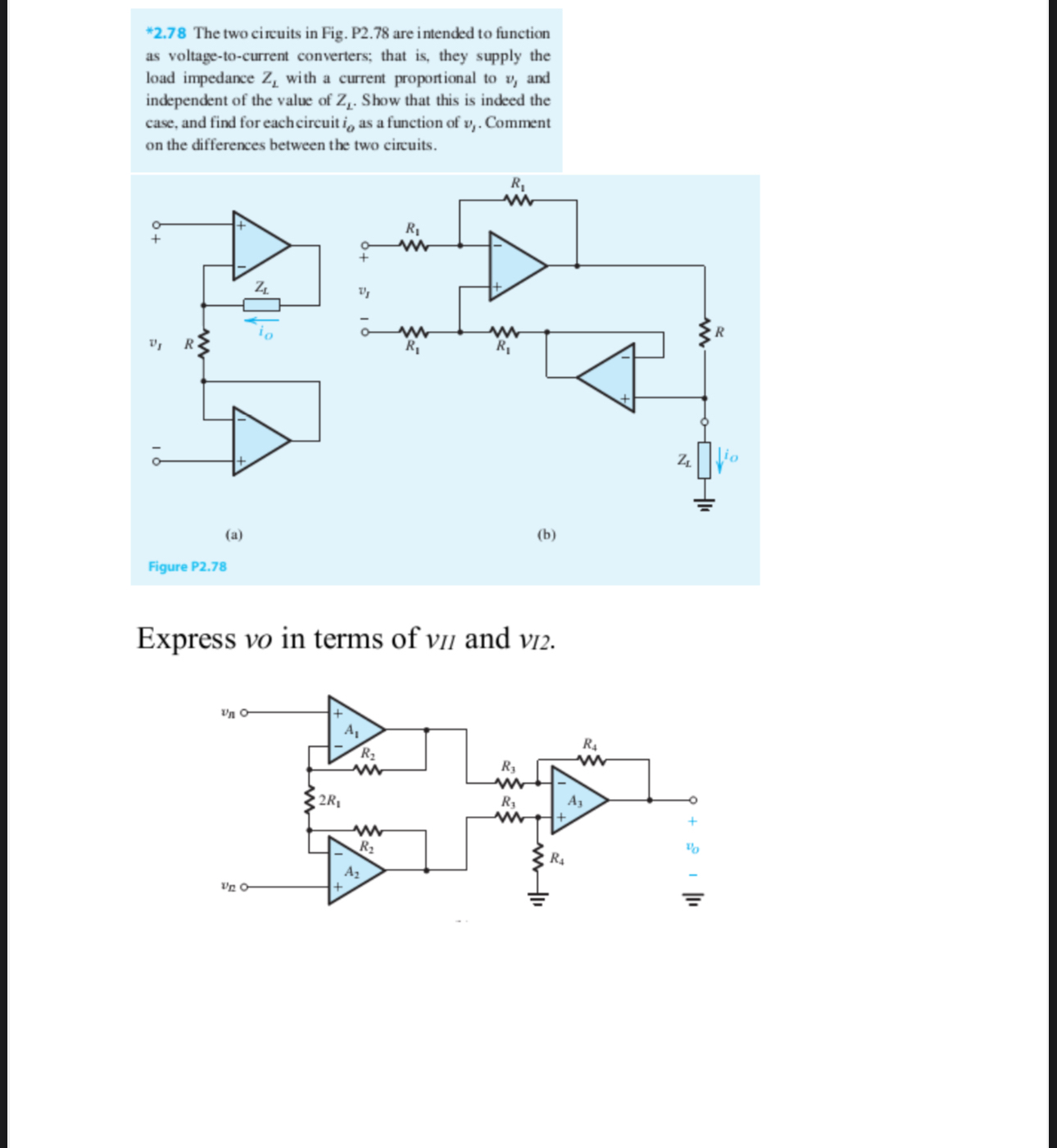
The two circuits in Fig. P are intended to function as voltagetocurrent converters; that is they supply the load impedance with a current proportional to and independent of the value of Show that this is indeed the case, and find for each circuit as a function of Comment on the differences between the two circuits.
Express in terms of and
Step by Step Solution
There are 3 Steps involved in it
1 Expert Approved Answer
Step: 1 Unlock

Question Has Been Solved by an Expert!
Get step-by-step solutions from verified subject matter experts
Step: 2 Unlock
Step: 3 Unlock