

Question: 5) a) As shown in the figure, the input voltage is 120 Volts (RMS) and the diode voltages are 0.7 Volts. Design the circuit for
5)
a) As shown in the figure, the input voltage is 120 Volts (RMS) and the diode voltages are 0.7 Volts. Design the circuit for the two output voltages given below and find the number of turns of the transformer.
i) 10 V
ii) 100 V

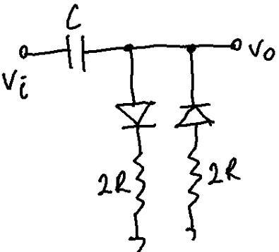
b) Consider a circuit using a Si diode and a 10 k ohm resistor. Design this clipper circuit with the following output intervals;
i) -0.7 V and above
ii) +2.1 V and above
iii) ± 1.4 V
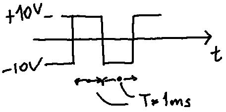
c) The input voltage is given by Vi for the clamper circuit shown in the figure. Give the output voltage with analytical solution. Plot the graph of VO - Vi.
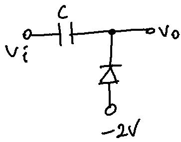
D1 fine Vs
Step by Step Solution
3.38 Rating (164 Votes )
There are 3 Steps involved in it

Get step-by-step solutions from verified subject matter experts