

Question: 2. A general fourbar linkage configuration and its notation are shown in the below figure. The link lengths, coupler point location, and the relevant
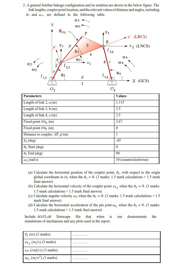
2. A general fourbar linkage configuration and its notation are shown in the below figure. The link lengths, coupler point location, and the relevant values of distance and angles, including 8, and w, are defined in the following table. Y .3 W3 RPA P 12 B 3 83 b 03 134 4 c 004 x' (LRCS) 014 x2 (LNCS) 2 123 a 04 02 d 11A X (GCS) 1 002 11,2 Parameters 02 Length of link 2, a (m) Length of link 3, b(m) Length of link 4, c (m) Fixed point 04x (m) Fixed point 04y (m) Distance to coupler, AP, p (m) 83 (deg) 8 Start (deg) 8 End (deg) w2 (rad/s) Values 1.115 2.5 2.5 2.67 0 1 -45 0 90 10 (counterclockwise) (a) Calculate the horizontal position of the coupler point, Px, with respect to the origin global coordinate in O2 when the 82 = 0. (3 marks: 1.5 mark calculations + 1.5 mark final answer) (b) Calculate the horizontal velocity of the coupler point vp, when the 0 = 0. (3 marks: 1.5 mark calculations +1.5 mark final answer) (c) Calculate angular velocity w3 when the 82 = 0. (3 marks: 1.5 mark calculations +1.5 mark final answer) (d) Calculate the horizontal acceleration of the pin joint ap, when the = 0. (3 marks: 1.5 mark calculations +1.5 mark final answer) Include MATLAB Simscape file that when is run desmonstrate the simulations of mechanism and any plots used in the report. Px (m) (3 marks) Vpx (m/s) (3 marks) w3 (rad/s) (3 marks) ap, (m/s) (3 marks)
Step by Step Solution
There are 3 Steps involved in it

Get step-by-step solutions from verified subject matter experts