

Question: 2. A pulse input x(t) is applied to the RC circuit shown below. The expected capacitor voltage output, y(t), is also shown. J(o)- Note :
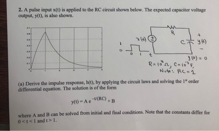
2. A pulse input x(t) is applied to the RC circuit shown below. The expected capacitor voltage output, y(t), is also shown. J(o)- Note : RC = 1 )Derive the impulse response, h(), by applying the circuit laws and solving the 1t order differential equation. The solution is of the form y(t) =Ae-t/(RC) + B where A and B can be solved from initial and final conditions. Note that the constants differ for 0
Step by Step Solution
There are 3 Steps involved in it

Get step-by-step solutions from verified subject matter experts