

Question: 2. Consider the controller assembly shown in the following Figure. The assembly of this product first involves securing a series of assemblies to the
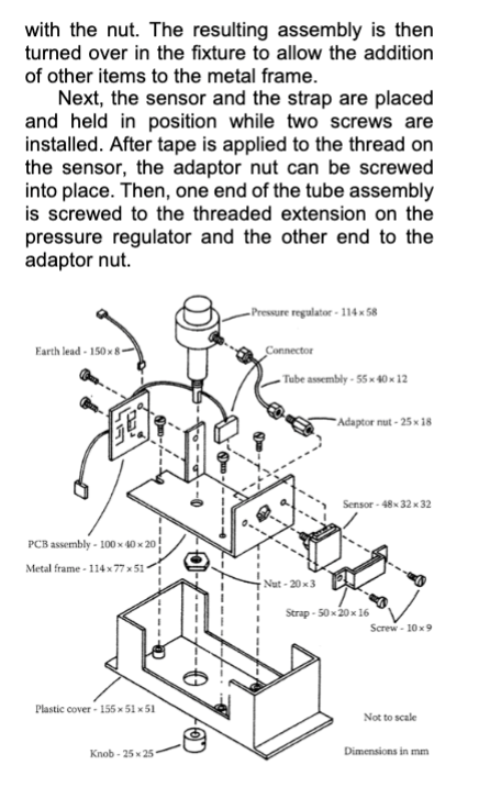
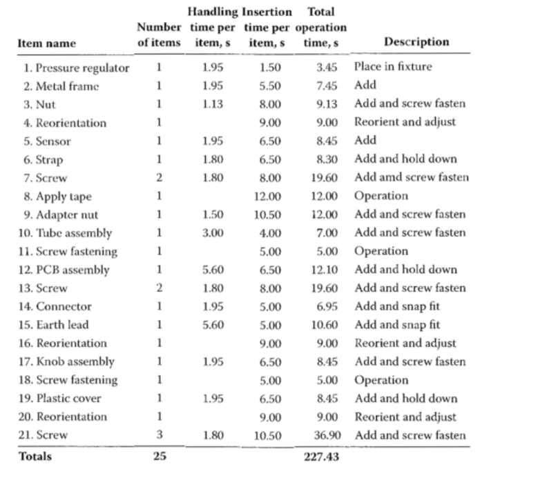
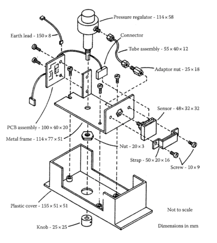
2. Consider the controller assembly shown in the following Figure. The assembly of this product first involves securing a series of assemblies to the metal frame using screws, connecting these assemblies together in various ways, and then securing the resulting assembly into the plastic cover, again using screws. An undesirable feature of the design of the plastic cover is that the small subassemblies must be fastened to the metal frame before the metal frame can be secured to the plastic cover. Following the part sequence in the CE Worksheet, as included to the right, assembly starts by placing the pressure regulator (a purchased item) upside-down into a fixture. The metal frame is placed onto the projecting spindle of the pressure regulator and secured with the nut. The resulting assembly is then turned over in the fixture to allow the addition of other items to the metal frame. Next, the sensor and the strap are placed and held in position while two screws are installed. After tape is applied to the thread on the sensor, the adaptor nut can be screwed into place. Then, one end of the tube assembly is screwed to the threaded extension on the pressure regulator and the other end to the adaptor nut. Earth lead-150x8- 157 Pressure regulator-114x58 Connector Tube assembly-55x40x12 Adaptor nut-25 x 18 Sensor-48x32x32 PCB assembly-100x40x20 Metal frame-114 x 77 x 51 Nut-20x3 Strap-50x20x16 Screw-10x9 Plastic cover 155 x 51 x 51 Knob-25x25 Not to scale Dimensions in mm Handling Insertion Total Number time per time per operation Item name of items item, s item, s time, s Description 1. Pressure regulator 1 1.95 1.50 3.45 Place in fixture 2. Metal frame 1 1.95 5.50 7.45 Add 3. Nut 1 1.13 8.00 9.13 Add and screw fasten 4. Reorientation 1 9.00 9.00 Reorient and adjust 5. Sensor 1 1.95 6.50 8.45 Add 6. Strap 1 1.80 6.50 8.30 Add and hold down 7. Screw 2 1.80 8.00 19.60 Add amd screw fasten 8. Apply tape 1 12.00 12.00 Operation 9. Adapter nut 1 1.50 10.50 12.00 Add and screw fasten 10. Tube assembly 1 3.00 4.00 7.00 Add and screw fasten 11. Screw fastening 1 5.00 5.00 Operation 12. PCB assembly 1 5.60 6.50 12.10 Add and hold down 13. Screw 2 1.80 8.00 19.60 Add and screw fasten 14. Connector 1 1.95 5.00 6.95 Add and snap fit 15. Earth lead 1 5.60 5.00 10.60 Add and snap fit 16. Reorientation 1 9.00 9.00 Reorient and adjust 17. Knob assembly 1 1.95 6.50 8.45 Add and screw fasten 18. Screw fastening 1 5.00 5.00 Operation 19. Plastic cover 1 1.95 6.50 8.45 Add and hold down 20. Reorientation 1 9.00 9.00 Reorient and adjust 21. Screw 3 1.80 10.50 36.90 Add and screw fasten Totals 25 227.43 The printed circuit board (PCB) assembly is then positioned and held in place while two screws are installed, after which its connector is snapped into the sensor and the earth lead is snapped into place. The whole assembly must be turned over once again to allow the positioning and holding of the knob assembly while the screw- fastening operation can be carried out. Finally, the plastic cover is placed in position and the entire assembly is turned over for the third time to allow the three screws to be inserted. Many aspects of the design might be improved. You are asked to (1) calculate the Design Efficiency for this design; (2) redesign the product such that the Design Efficiency is 15% or higher. Provide a drawing (either by hand or by software) of the redesign; (3) complete the CE worksheet to explicitly show how your new Design Efficiency is calculated. Earth lead - 150x8- E PCB assembly 100 x 40 x 20 Metal frame-114x7751 Plastic cover - 155 5151 -Pressure regulator - 114x58 Connector Tube assembly - 55 x 40 x 12 Adaptor nut - 25 x 18 Sensor-48x32x32 Nut - 20x3 Strap - 5020 16 Screw-10x9 Not to scale Knob 25x25 Dimensions in mm
Step by Step Solution
There are 3 Steps involved in it

Get step-by-step solutions from verified subject matter experts