

Question: 2 . Consider the dc - to - dc conversion system shown in Figure P 2 . 4 . The system is configured with two
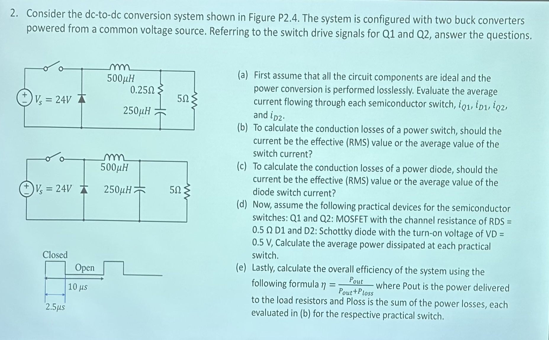
Consider the dctodc conversion system shown in Figure P The system is configured with two buck converters powered from a common voltage source. Referring to the switch drive signals for Q and Q answer the questions.
a First assume that all the circuit components are ideal and the power conversion is performed losslessly. Evaluate the average current flowing through each semiconductor switch, iQ iD iQ and iD
b To calculate the conduction losses of a power switch, should the current be the effective RMS value or the average value of the switch current?
c To calculate the conduction losses of a power diode, should the current be the effective RMS value or the average value of the diode switch current?
d Now, assume the following practical devices for the semiconductor switches: Q and Q: MOSFET with the channel resistance of RDS Omega mathrmD and D: Schottky diode with the turnon voltage of VD V Calculate the average power dissipated at each practical switch.
e Lastly, calculate the overall efficiency of the system using the following formula etafracPtext out Ptext out Ptext loss where Pout is the power delivered to the load resistors and Ploss is the sum of the power losses, each evaluated in b for the respective practical switch.
Step by Step Solution
There are 3 Steps involved in it
1 Expert Approved Answer
Step: 1 Unlock

Question Has Been Solved by an Expert!
Get step-by-step solutions from verified subject matter experts
Step: 2 Unlock
Step: 3 Unlock