

Question: 2. Consider the following RRP manipulator with the schematic below, which is the first 3 joints of a manipulator you have seen before in
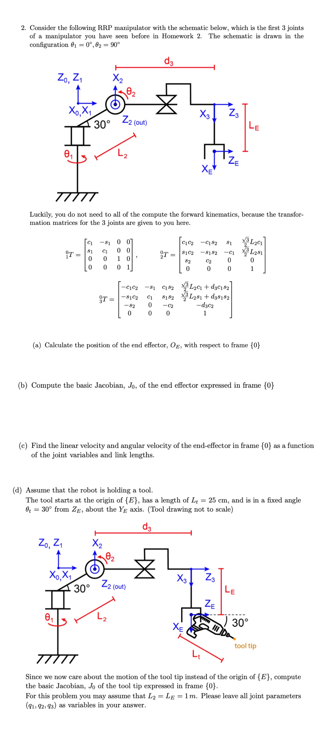
2. Consider the following RRP manipulator with the schematic below, which is the first 3 joints of a manipulator you have seen before in Homework 2. The schematic is drawn in the configuration 0 = 0, 02 = 90 d3 Zo, Z X0,X1 X 3. Z3 30 Z2 (out) LE ZE Luckily, you do not need to all of the compute the forward kinematics, because the transfor- mation matrices for the 3 joints are given to you here. -C182 $1 3L2C1 T= 5500 -81 0 0 [C1 C2 C1 00 T= S1C2 -8182 -C1 L281 0 1 0 82 C2 0 0 0 0 1 0 0 0 1 -C1C2 -81 C182 L2c1d3c82 L281+d38182 T = -81C2 C1 8182 = -82 0 -C2 -d3c2 0 0 0 1 (a) Calculate the position of the end effector, OE, with respect to frame {0} (b) Compute the basic Jacobian, Jo, of the end effector expressed in frame {0} (c) Find the linear velocity and angular velocity of the end-effector in frame {0} as a function of the joint variables and link lengths. (d) Assume that the robot is holding a tool. The tool starts at the origin of {E}, has a length of Lt = 25 cm, and is in a fixed angle 0 = 30 from ZE, about the YE axis. (Tool drawing not to scale) d3 Zo, Z X2 X3 Z3 X0,X1 30 Z2 (out) LE ZE www 30 01 XE tool tip Since we now care about the motion of the tool tip instead of the origin of {E}, compute the basic Jacobian, Jo of the tool tip expressed in frame {0}. For this problem you may assume that L2 = (91, 92, 93) as variables in your answer. = LE 1m. Please leave all joint parameters
Step by Step Solution
There are 3 Steps involved in it

Get step-by-step solutions from verified subject matter experts