

Question: 2. Finite State Machine Within a hard drive controller, a four-phase stepper motor (outputs Pho, Phi, Ph2 & Ph3) controls the position of the read/write
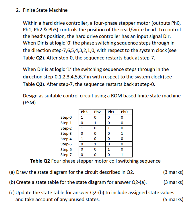
2. Finite State Machine Within a hard drive controller, a four-phase stepper motor (outputs Pho, Phi, Ph2 & Ph3) controls the position of the read/write head. To control the head's position, the hard drive controller has an input signal Dir. When Dir is at logic 'O the phase switching sequence steps through in the direction step-7,6,5,4,3,2,1,0, with respect to the system clock(see Table Q2). After step-0, the sequence restarts back at step-7. 0 0 0 0 1 1 0 0 When Dir is at logic 'l'the switching sequence steps through in the direction step-0,1,2,3,4,5,6,7 in with respect to the system clock (see Table Q2). After step-7, the sequence restarts back at step-o. Design as suitable control circuit using a ROM based finite state machine (FSM). Ph3 Ph2 Ph1 Pho Step-o 1 0 0 Step-1 Step-2 Step-3 Step-4 Step-5 Step-6 Step-7 Table Q2 Four phase stepper motor coil switching sequence (a) Draw the state diagram for the circuit described in Q2. (3 marks) (b) Create a state table for the state diagram for answer Q2-(a). (3 marks) (c) Update the state table for answer Q2-(b) to include assigned state values and take account of any unused states. (5 marks) 1 0 0 1 0 1 0 0 0 1 0 0 0 0 1 0 0 0 0 0 1 2. Finite State Machine Within a hard drive controller, a four-phase stepper motor (outputs Pho, Phi, Ph2 & Ph3) controls the position of the read/write head. To control the head's position, the hard drive controller has an input signal Dir. When Dir is at logic 'O the phase switching sequence steps through in the direction step-7,6,5,4,3,2,1,0, with respect to the system clock(see Table Q2). After step-0, the sequence restarts back at step-7. 0 0 0 0 1 1 0 0 When Dir is at logic 'l'the switching sequence steps through in the direction step-0,1,2,3,4,5,6,7 in with respect to the system clock (see Table Q2). After step-7, the sequence restarts back at step-o. Design as suitable control circuit using a ROM based finite state machine (FSM). Ph3 Ph2 Ph1 Pho Step-o 1 0 0 Step-1 Step-2 Step-3 Step-4 Step-5 Step-6 Step-7 Table Q2 Four phase stepper motor coil switching sequence (a) Draw the state diagram for the circuit described in Q2. (3 marks) (b) Create a state table for the state diagram for answer Q2-(a). (3 marks) (c) Update the state table for answer Q2-(b) to include assigned state values and take account of any unused states. (5 marks) 1 0 0 1 0 1 0 0 0 1 0 0 0 0 1 0 0 0 0 0 1
Step by Step Solution
There are 3 Steps involved in it

Get step-by-step solutions from verified subject matter experts