

Question: Problem 14 (25 points) 1. (10 points) Figure 5 shows a Moore finite state machine and all the subdiagrams in the case structure within the
Problem 14 (25 points)
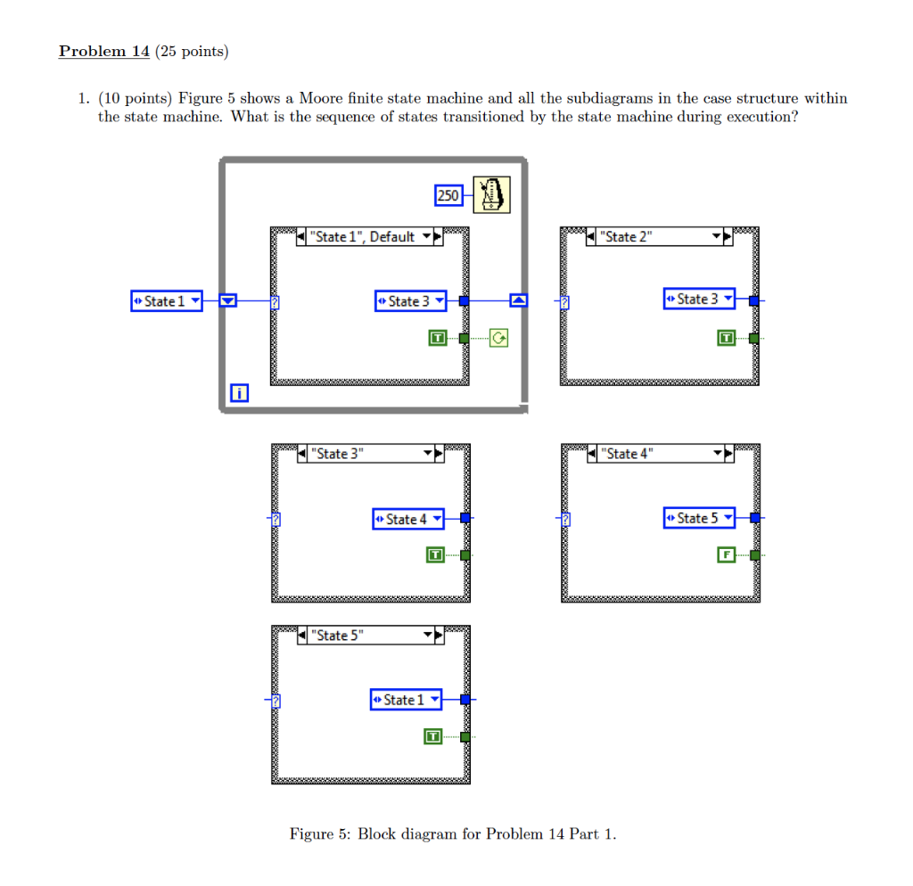
1. (10 points) Figure 5 shows a Moore finite state machine and all the subdiagrams in the case structure within
the state machine. What is the sequence of states transitioned by the state machine during execution?
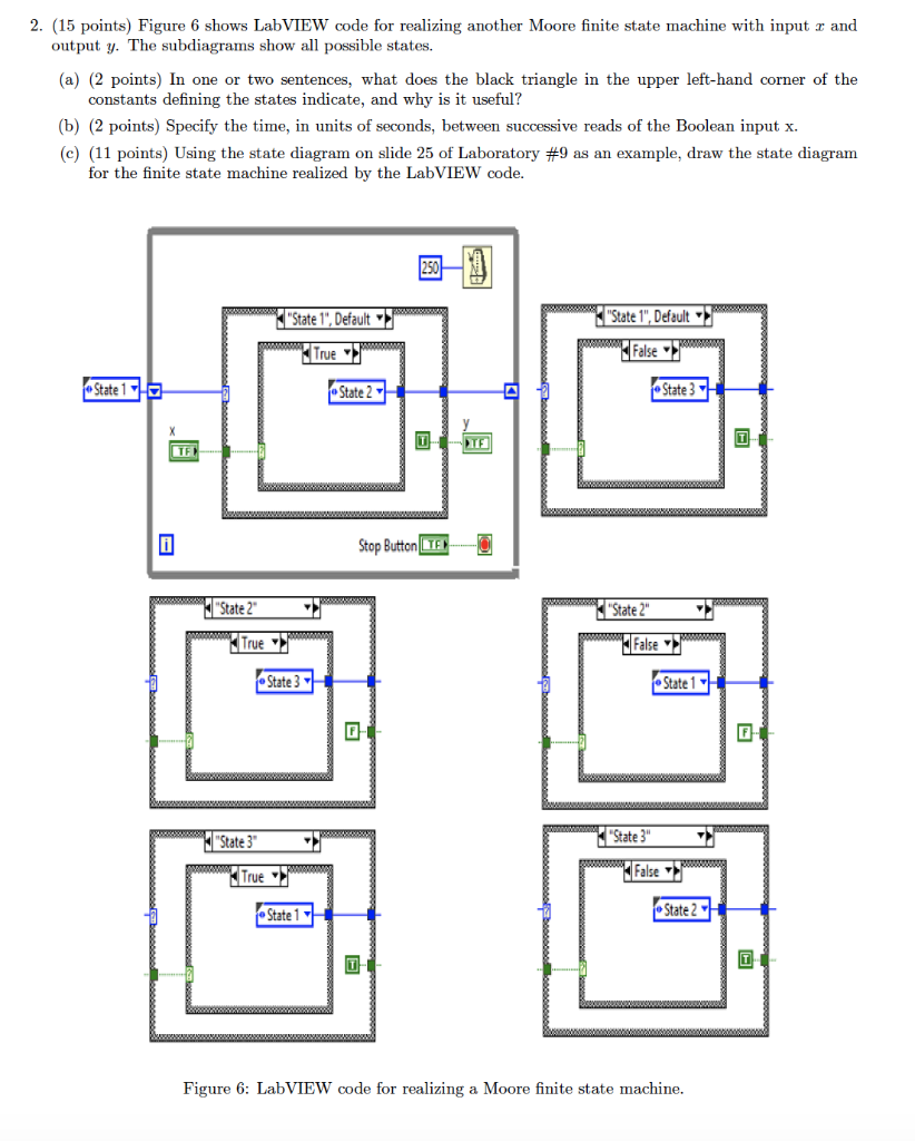
2. (15 points) Figure 6 shows LabVIEW code for realizing another Moore finite state machine with input x and
output y. The subdiagrams show all possible states.
(a) (2 points) In one or two sentences, what does the black triangle in the upper left-hand corner of the
constants defining the states indicate, and why is it useful?
(b) (2 points) Specify the time, in units of seconds, between successive reads of the Boolean input x.
(c) (11 points) Using the state diagram on slide 25 of Laboratory #9 as an example, draw the state diagram
for the finite state machine realized by the LabVIEW code.
Problem 14 (25 points) 1. (10 points) Figure 5 shows a Moore finite state machine and all the subdiagrams in the case structure within the state machine. What is the sequence of states transitioned by the state machine during execution? "State 1", Default "State 2" State 1 State 3 4 State 3- w "State 3" "State 4" State 4 State 5 "State 5" State 1 Figure 5: Block diagram for Problem 14 Part 1. 2. (15 points) Figure 6 shows LabVIEW code for realizing another Moore finite state machine with input r and output y. The subdiagrams show all possible states. (a) (2 points) In one or two sentences, what does the black triangle in the upper left-hand corner of the constants defining the states indicate, and why is it useful? (b) (2 points) Specify the time, in units of seconds, between successive reads of the Boolean input x. (c) (11 points) Using the state diagram on slide 25 of Laboratory #9 as an example, draw the state diagram for the finite state machine realized by the LabVIEW code. www."State 1", Default "State 1", Default True False www State 15 State2 State 3 Stop Button TEO State 2" "State 2" True False - State 1 State 3 nnaa SEMASA wwwwwwwwwwwwwwwwwwwwwww "State 3" 3 State 3" True False - State 2+1 State 1 boccolo Figure 6: LabVIEW code for realizing a Moore finite state machine. Problem 14 (25 points) 1. (10 points) Figure 5 shows a Moore finite state machine and all the subdiagrams in the case structure within the state machine. What is the sequence of states transitioned by the state machine during execution? "State 1", Default "State 2" State 1 State 3 4 State 3- w "State 3" "State 4" State 4 State 5 "State 5" State 1 Figure 5: Block diagram for Problem 14 Part 1. 2. (15 points) Figure 6 shows LabVIEW code for realizing another Moore finite state machine with input r and output y. The subdiagrams show all possible states. (a) (2 points) In one or two sentences, what does the black triangle in the upper left-hand corner of the constants defining the states indicate, and why is it useful? (b) (2 points) Specify the time, in units of seconds, between successive reads of the Boolean input x. (c) (11 points) Using the state diagram on slide 25 of Laboratory #9 as an example, draw the state diagram for the finite state machine realized by the LabVIEW code. www."State 1", Default "State 1", Default True False www State 15 State2 State 3 Stop Button TEO State 2" "State 2" True False - State 1 State 3 nnaa SEMASA wwwwwwwwwwwwwwwwwwwwwww "State 3" 3 State 3" True False - State 2+1 State 1 boccolo Figure 6: LabVIEW code for realizing a Moore finite state machine
Step by Step Solution
There are 3 Steps involved in it

Get step-by-step solutions from verified subject matter experts