

Question: 2 For the frame shown in the figure below, develop element stiffness matrices in the global co - ordinate system. Assume that A = 1
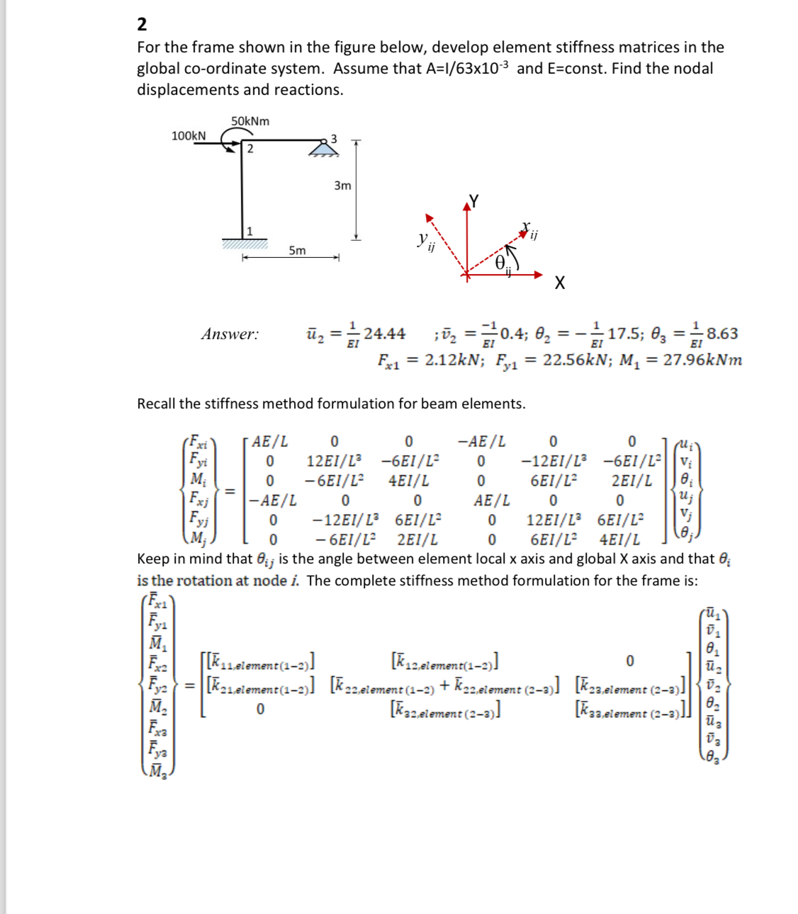
For the frame shown in the figure below, develop element stiffness matrices in the global coordinate system. Assume that and const. Find the nodal displacements and reactions.
Answer:
;;
;;
Recall the stiffness method formulation for beam elements.
Keep in mind that is the angle between element local axis and global axis and that is the rotation at node The complete stiffness method formulation for the frame is:
Step by Step Solution
There are 3 Steps involved in it
1 Expert Approved Answer
Step: 1 Unlock

Question Has Been Solved by an Expert!
Get step-by-step solutions from verified subject matter experts
Step: 2 Unlock
Step: 3 Unlock