

Question: Use the finite element approach ( the element formulation approach ) to solve for displacements and stresses in the structure shown in Figure 1 .
Use the finite element approach the "element formulation" approach to solve for displacements
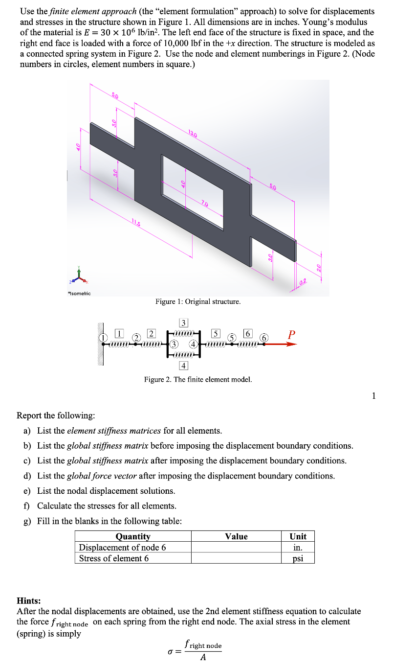
and stresses in the structure shown in Figure All dimensions are in inches. Young's modulus
of the material is The left end face of the structure is fixed in space, and the
right end face is loaded with a force of in the direction. The structure is modeled as
a connected spring system in Figure Use the node and element numberings in Figure Node
numbers in circles, element numbers in square.
Report the following:
a List the element stiffness matrices for all elements.
b List the global stiffness matrix before imposing the displacement boundary conditions.
c List the global stiffness matrix after imposing the displacement boundary conditions.
d List the global force vector after imposing the displacement boundary conditions.
e List the nodal displacement solutions.
f Calculate the stresses for all elements.
g Fill in the blanks in the following table:
Hints:
After the nodal displacements are obtained, use the nd element stiffness equation to calculate
the force on each spring from the right end node. The axial stress in the element
spring is simply
The answers can be all done in excel, please show the spreadsheet with the excel doc and formulas used.
Step by Step Solution
There are 3 Steps involved in it
1 Expert Approved Answer
Step: 1 Unlock

Question Has Been Solved by an Expert!
Get step-by-step solutions from verified subject matter experts
Step: 2 Unlock
Step: 3 Unlock