

Question: Fig. 1 shows the one-line diagram of a 5-bus power system with line impedances and voltage levels in per-unit. The circuit of Fig. 1
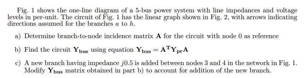
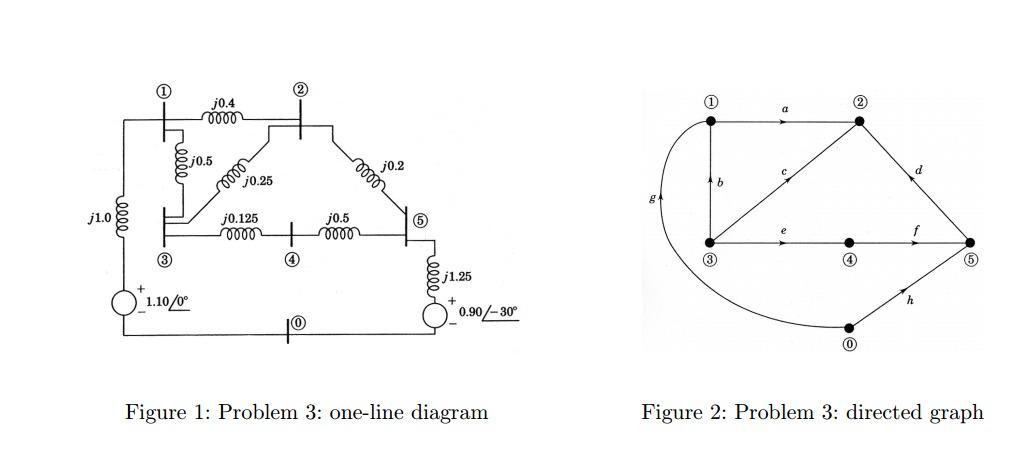
Fig. 1 shows the one-line diagram of a 5-bus power system with line impedances and voltage levels in per-unit. The circuit of Fig. 1 has the linear graph shown in Fig. 2, with arrows indicating directions assumed for the branches a to h. a) Determine branch-to-node incidence matrix A for the circuit with node 0 as reference Find the circuit Ybus using equation Ypus = ATYprA c) A new branch having impedance j0.5 is added between nodes 3 and 4 in the network in Fig. 1. Modify Ypus matrix obtained in part b) to account for addition of the new branch. 2 j0.4 j0.2 lelll j0.5 b j0.25 j0.125 ell j1.0 j0.5 f 3 j1.25 OL.10/0 0.90/-30 0) Figure 2: Problem 3: directed graph Figure 1: Problem 3: one-line diagram
Step by Step Solution
There are 3 Steps involved in it

Get step-by-step solutions from verified subject matter experts