

Question: 2. Many chemical plants use pneumatic system to control instruments. Below diagram shows the air flow from air compressor, buffer tank to the system consumers.
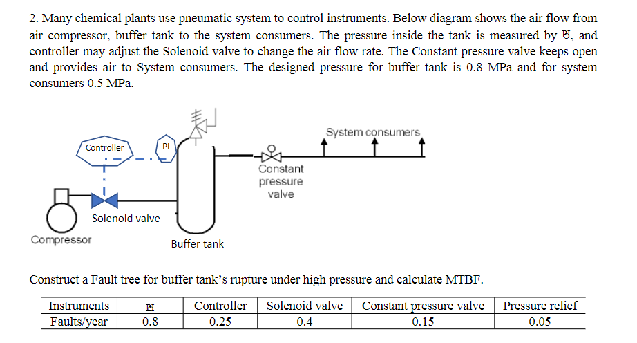
2. Many chemical plants use pneumatic system to control instruments. Below diagram shows the air flow from air compressor, buffer tank to the system consumers. The pressure inside the tank is measured by HI, and controller may adjust the Solenoid valve to change the air flow rate. The Constant pressure valve keeps open and provides air to System consumers. The designed pressure for buffer tank is 0.8 MPa and for system consumers 0.5 MPa. att System consumers Controller PI Constant pressure valve Solenoid valve Compressor Buffer tank Construct a Fault tree for buffer tanks rupture under high pressure and calculate MTBF. Instruments Faults/year PI 0.8 Controller 0.25 Solenoid valve 0.4 Constant pressure valve 0.15 Pressure relief 0.05
Step by Step Solution
There are 3 Steps involved in it

Get step-by-step solutions from verified subject matter experts