

Question: 236 Chapter 8. RTL Verilog design examples 18-5: Design a digital system that finds the maximum difference (diff) between any two 8-bit numbers in a
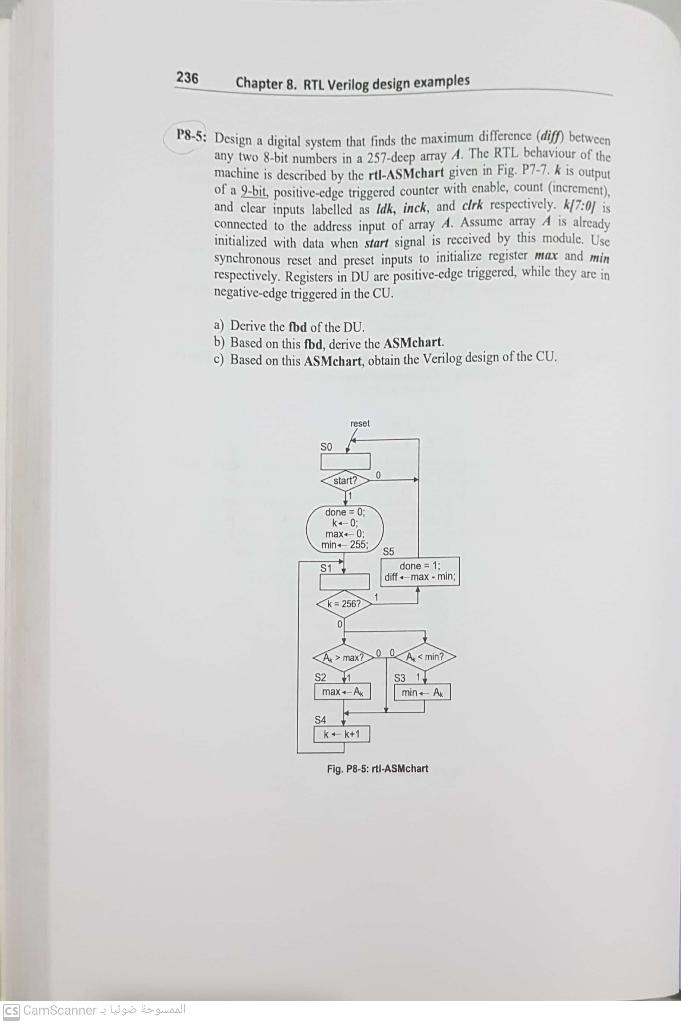
236 Chapter 8. RTL Verilog design examples 18-5: Design a digital system that finds the maximum difference (diff) between any two 8-bit numbers in a 257-deep array A. The RTL behaviour of the machine is described by the rtl-ASMchart given in Fig. P7-7. k is output of a 9-bit , positive-edge triggered counter with enable, count (increment), and clear inputs labelled as Idk, inck, and clrk respectively. k17:01 is connected to the address input of array A. Assume array A is already initialized with data when start signal is received by this module. Use synchronous reset and preset inputs to initialize register max and min respectively. Registers in DU are positive-edge triggered, while they are in negative-edge triggered in the CU. a) Derive the fbd of the DU. b) Based on this fbd, derive the ASMchart. c) Based on this ASMchart, obtain the Verilog design of the CU, reset So start? done = 0 kao max. 0 min. 255; S17 S5 done = 1 diff.-max-min; k = 2567 ol A > max? Amin? S2 11 S3 11 max-A min-All S4 kek+1 Fig. P8-5: rtl-ASMchart - cs CamScanner 236 Chapter 8. RTL Verilog design examples 18-5: Design a digital system that finds the maximum difference (diff) between any two 8-bit numbers in a 257-deep array A. The RTL behaviour of the machine is described by the rtl-ASMchart given in Fig. P7-7. k is output of a 9-bit , positive-edge triggered counter with enable, count (increment), and clear inputs labelled as Idk, inck, and clrk respectively. k17:01 is connected to the address input of array A. Assume array A is already initialized with data when start signal is received by this module. Use synchronous reset and preset inputs to initialize register max and min respectively. Registers in DU are positive-edge triggered, while they are in negative-edge triggered in the CU. a) Derive the fbd of the DU. b) Based on this fbd, derive the ASMchart. c) Based on this ASMchart, obtain the Verilog design of the CU, reset So start? done = 0 kao max. 0 min. 255; S17 S5 done = 1 diff.-max-min; k = 2567 ol A > max? Amin? S2 11 S3 11 max-A min-All S4 kek+1 Fig. P8-5: rtl-ASMchart - cs CamScanner
Step by Step Solution
There are 3 Steps involved in it

Get step-by-step solutions from verified subject matter experts