

Question: 2.71 The circuit shown in Fig. P2.71 is a representation of a versatile, commercially available IC, the INA105, manufactured by Burr-Brown and known as
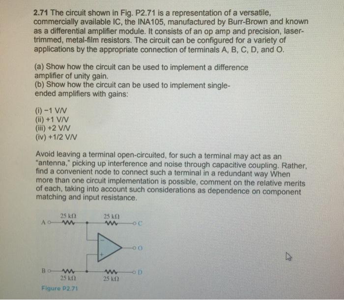
2.71 The circuit shown in Fig. P2.71 is a representation of a versatile, commercially available IC, the INA105, manufactured by Burr-Brown and known as a differential amplifier module. It consists of an op amp and precision, laser- trimmed, metal-film resistors. The circuit can be configured for a variety of applications by the appropriate connection of terminals A, B, C, D, and O. (a) Show how the circuit can be used to implement a difference amplifier of unity gain. (b) Show how the circuit can be used to implement single- ended amplifiers with gains: (i) -1 VN (ii) +1 V/V (iii) +2 VN (iv) +1/2 V/V Avoid leaving a terminal open-circuited, for such a terminal may act as an "antenna," picking up interference and noise through capacitive coupling. Rather, find a convenient node to connect such a terminal in a redundant way When more than one circuit implementation is possible, comment on the relative merits of each, taking into account such considerations as dependence on component matching and input resistance. 25 kn www www 25 Figure P2.711 25 www www 25 k OC -0.0 D
Step by Step Solution
3.38 Rating (151 Votes )
There are 3 Steps involved in it
If you give differential input Vid VV by connecting C to and D to ground Since Vp 0 b superposition ... View full answer

Get step-by-step solutions from verified subject matter experts