

Question: 3 . 2 9 Derive a mathematical model for the translatory mechanical system of Figure 3 . 6 7 ( a ) . Use MATLAB
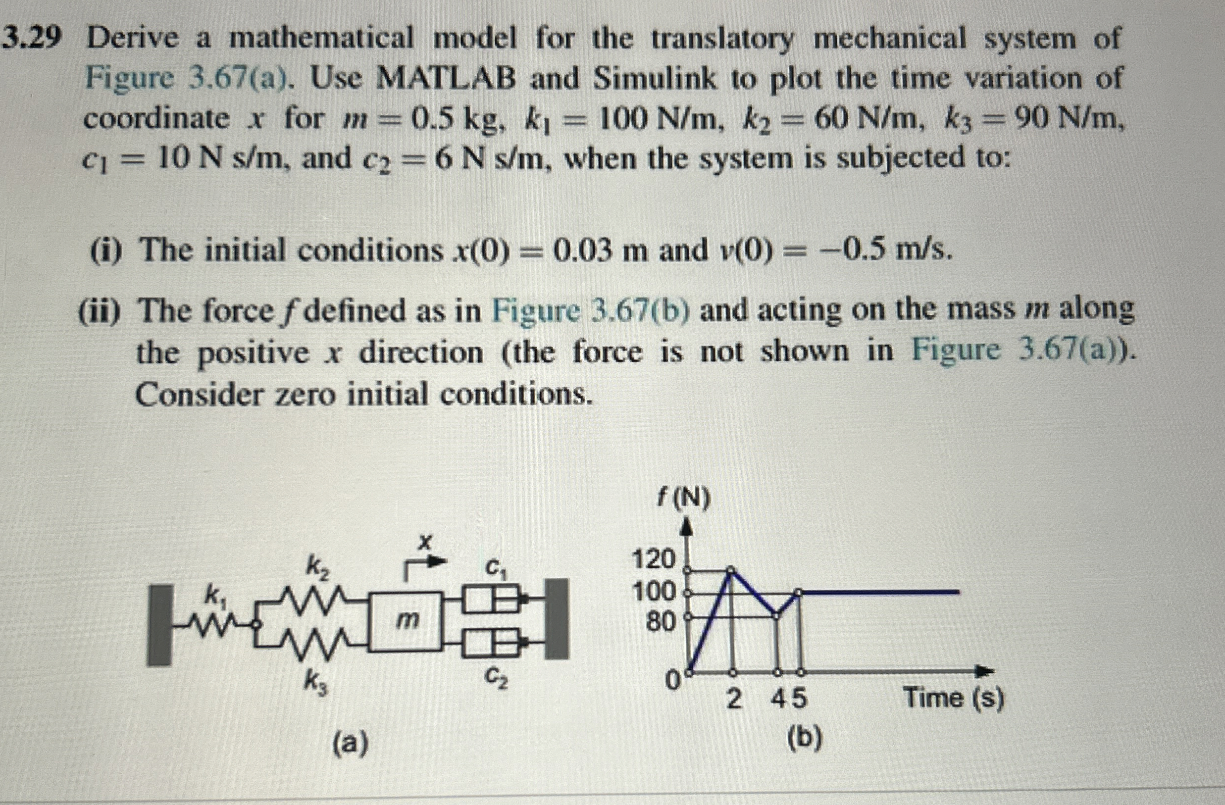
Derive a mathematical model for the translatory mechanical system of
Figure a Use MATLAB and Simulink to plot the time variation of
coordinate for
and when the system is subjected to:
i The initial conditions and
ii The force defined as in Figure b and acting on the mass along
the positive direction the force is not shown in Figure a
Consider zero initial conditions.
a
b
Step by Step Solution
There are 3 Steps involved in it
1 Expert Approved Answer
Step: 1 Unlock

Question Has Been Solved by an Expert!
Get step-by-step solutions from verified subject matter experts
Step: 2 Unlock
Step: 3 Unlock