

Question: 3. (a) Based on Figure 1, explain the function of the following items: CPU Bus Control Signal PC + Address Bus Decoder MAR Memory MBR
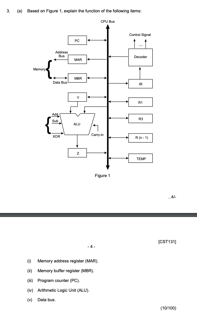
3. (a) Based on Figure 1, explain the function of the following items: CPU Bus Control Signal PC + Address Bus Decoder MAR Memory MBR Data Bus IR Y R1 Add Sub R3 ALU XOR Carry-in R (n-1) TEMP Figure 1 ...4/ [CST131] - 4- (0) Memory address register (MAR). (ii) Memory buffer register (MBR). (iii) Program counter (PC). (iv) Arithmetic Logic Unit (ALU). (v) Data bus. (10/100)
Step by Step Solution
There are 3 Steps involved in it
1 Expert Approved Answer
Step: 1 Unlock

Question Has Been Solved by an Expert!
Get step-by-step solutions from verified subject matter experts
Step: 2 Unlock
Step: 3 Unlock