

Question: Microarchitecture/Microcode 1. The following is a set of microinstructions (a - g) developed for the microarchitecture presented in class on Slide 18 of the Power
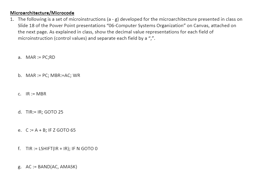
Microarchitecture/Microcode 1. The following is a set of microinstructions (a - g) developed for the microarchitecture presented in class on Slide 18 of the Power Point presentations "06-Computer Systems Organization" on Canvas, attached on the next page. As explained in class, show the decimal value representations for each field of microinstruction (control values) and separate each field by a,". a. MAR := PC;RD b. MAR := PC; MBR:=AC; WR c. IR := MBR d. TIR:= IR; GOTO 25 e. C:= A +B; IF Z GOTO 65 f. TIR := LSHIFT(IR + IR); IF N GOTO O g. AC:= BAND(AC, AMASK) A bus B bus 4 4 C bus 16 MIR Bits 1 2 2 2 11111 AC UMI MO NALUSH BIASAN XP MMAW PC " decoder c B A ADOR 7 LL AC 16/ B decoder 1 AMUX COND ALU 0 - Alatch 0.No jump 0.A.B 1 - MBR 1. Jump IN1 1A AND B 2. Jump 2-1 2-4 3 - Jump always 3-A SH o. No shift 1.Shirt right bit 2-Shift left 1 bit 3 - not used) SP 16 IR decoder MBR, MAR, RD, WR, ENC 0. No - The microinstruction layout for controlling the data path of Fig. 4-8. 1 Yes TIR 0 3 Clock 2 Subcycles +1 MBR := AC 1 2000 -1 16 registers 1 AMASK Mmux SMASK I Increment MPC A latch Blatch 256 x 32 Control Store MAR | MIR AC MI MR 20100d! D MM MBR 1 ADDR E RR XD Amux F A la ch Lo- Address out Blatch N Micro seq. Zlogic ALU Mo Data in To address bus MAR To data hue RO MBR M2 M3 *M1 A- AMpx Shifter N For F1 ALU So Shifter S1 RD WR Data out Microarchitecture/Microcode 1. The following is a set of microinstructions (a - g) developed for the microarchitecture presented in class on Slide 18 of the Power Point presentations "06-Computer Systems Organization" on Canvas, attached on the next page. As explained in class, show the decimal value representations for each field of microinstruction (control values) and separate each field by a,". a. MAR := PC;RD b. MAR := PC; MBR:=AC; WR c. IR := MBR d. TIR:= IR; GOTO 25 e. C:= A +B; IF Z GOTO 65 f. TIR := LSHIFT(IR + IR); IF N GOTO O g. AC:= BAND(AC, AMASK) A bus B bus 4 4 C bus 16 MIR Bits 1 2 2 2 11111 AC UMI MO NALUSH BIASAN XP MMAW PC " decoder c B A ADOR 7 LL AC 16/ B decoder 1 AMUX COND ALU 0 - Alatch 0.No jump 0.A.B 1 - MBR 1. Jump IN1 1A AND B 2. Jump 2-1 2-4 3 - Jump always 3-A SH o. No shift 1.Shirt right bit 2-Shift left 1 bit 3 - not used) SP 16 IR decoder MBR, MAR, RD, WR, ENC 0. No - The microinstruction layout for controlling the data path of Fig. 4-8. 1 Yes TIR 0 3 Clock 2 Subcycles +1 MBR := AC 1 2000 -1 16 registers 1 AMASK Mmux SMASK I Increment MPC A latch Blatch 256 x 32 Control Store MAR | MIR AC MI MR 20100d! D MM MBR 1 ADDR E RR XD Amux F A la ch Lo- Address out Blatch N Micro seq. Zlogic ALU Mo Data in To address bus MAR To data hue RO MBR M2 M3 *M1 A- AMpx Shifter N For F1 ALU So Shifter S1 RD WR Data out
Step by Step Solution
There are 3 Steps involved in it

Get step-by-step solutions from verified subject matter experts