

Question: 3. Consider the following assembly code: Instruction Description LOAD RI, M1 Read data from memory address M1 and store in RI, XOR R2.RIRI Logical Ex-OR
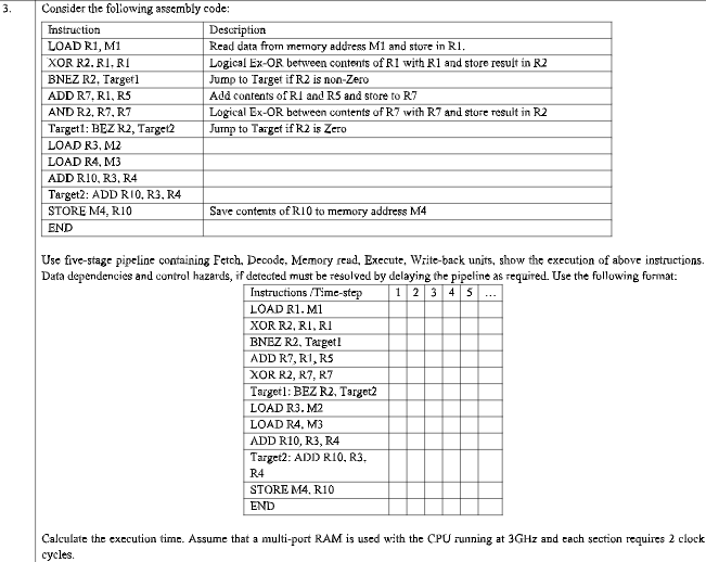
3. Consider the following assembly code: Instruction Description LOAD RI, M1 Read data from memory address M1 and store in RI, XOR R2.RIRI Logical Ex-OR between contents of R1 with R1 and store result in R2 BNEZ R2, Target1 Jump to Target if R2 is non-Zero ADD R7, R1, R5 Add contents of RI and RS and store to R7 AND R2, R7, R7 Logical Ex-OR between contents of R7 with R7 and store result in R2 Target1: BEZ R2, Target2 Jump to Target if R2 is Zero LOAD R3, M2 LOAD R4, M3 ADD RIO, R3, R4 Target2: ADD RIO, R3, R4 STORE M4, R10 Save contents of R10 to memory address M4 END Use five-stage pipeline containing Fetch, Decode, Memory read, Execute, Write-back units, show the execution of above instructions. Data dependencies and control hazards, if detected must be resolved by delaying the pipeline as required. Use the following format: Instructions /Time-step 1 2 3 4 5 LOAD R1. M1 XOR R2,RI, RI BNEZ R2, Target! ADD R7, R1, RS XOR R2, R7, R7 Target1: BEZ R2, Target2 LOAD R3. M2 LOAD R4. M3 ADD R10, R3, R4 Target2: ADD R10, R3, R4 STORE M4, R10 END Calculate the execution time. Assume that a multi-port RAM is used with the CPU running at 3GHz and each section requires 2 clock cycles
Step by Step Solution
There are 3 Steps involved in it

Get step-by-step solutions from verified subject matter experts