

Question: 3. From the APT program given below, sketch the geometry of the resultant part and the tool path according to each statement based on
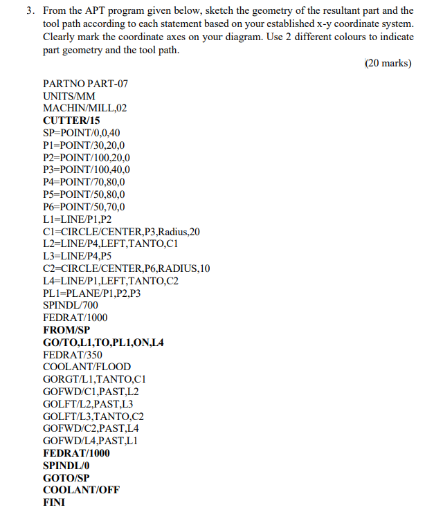
3. From the APT program given below, sketch the geometry of the resultant part and the tool path according to each statement based on your established x-y coordinate system. Clearly mark the coordinate axes on your diagram. Use 2 different colours to indicate part geometry and the tool path. PARTNO PART-07 UNITS/MM MACHIN/MILL,02 CUTTER/15 SP=POINT/0,0,40 P1=POINT/30,20,0 P2=POINT/100,20,0 P3-POINT/100,40,0 P4-POINT/70,80,0 P5-POINT/50,80,0 P6-POINT/50,70,0 L1=LINE/P1,P2 C1=CIRCLE/CENTER,P3,Radius,20 L2=LINE/P4,LEFT, TANTO,C1 L3=LINE/P4,P5 C2=CIRCLE/CENTER,P6,RADIUS,10 L4=LINE/P1,LEFT, TANTO,C2 PL1=PLANE/P1,P2,P3 SPINDL/700 FEDRAT/1000 FROM/SP GO/TO,LI,TO,PL1,ON,L4 FEDRAT/350 COOLANT/FLOOD GORGT/L1,TANTO,C1 GOFWD/C1,PAST,L2 GOLFT/L2,PAST,L3 GOLFT/L3, TANTO,C2 GOFWD/C2,PAST,L4 GOFWD/L4,PAST,LI FEDRAT/1000 SPINDL/0 GOTO/SP COOLANT/OFF FINI (20 marks)
Step by Step Solution
There are 3 Steps involved in it

Get step-by-step solutions from verified subject matter experts