

Question: 4 . 1 1 . Derive the local finite element stiffness matrix for a beam with combined transverse loading and axial force. The stiffness matrix
Derive the local finite element stiffness matrix for a beam with combined transverse loading and axial force.
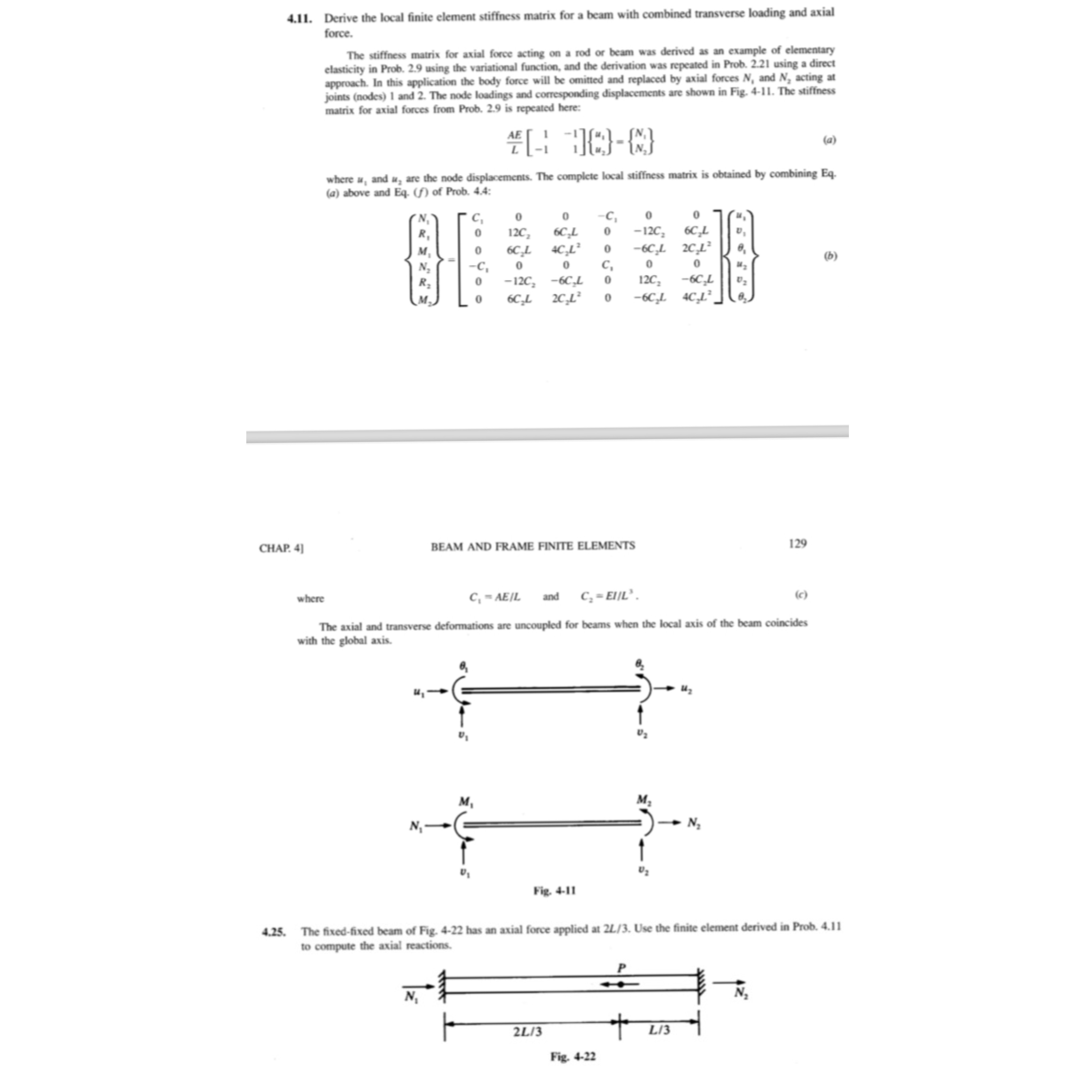
The stiffness matrix for axial force acting on a rod or beam was derived as an example of elementary elasticity in Prob. using the variational function, and the derivation was repeated in Prob. using a direct approach. In this application the body force will be omitted and replaced by axial forces and acting at joints nodes and The node loadings and corresponding displacements are shown in Fig. The stiffness matrix for axial forces from Prob. is repeated here:
where and are the node displacements. The complete local stiffness matrix is obtained by combining Eqa above and of Prob. :
where
and
c
The axial and transverse deformations are uncoupled for beams when the local axis of the beam coincides with the global axis.
The fixedfixed beam of Fig. has an axial force applied at Use the finite element derived in Prob. to compute the axial reactions.
solve problem only, is for reference as its mentioned in
Step by Step Solution
There are 3 Steps involved in it
1 Expert Approved Answer
Step: 1 Unlock

Question Has Been Solved by an Expert!
Get step-by-step solutions from verified subject matter experts
Step: 2 Unlock
Step: 3 Unlock