

Question: 4 . 4 . 4 . An industrial water - distribution system is schematically shown in Figure P 4 . 4 . 4 . The
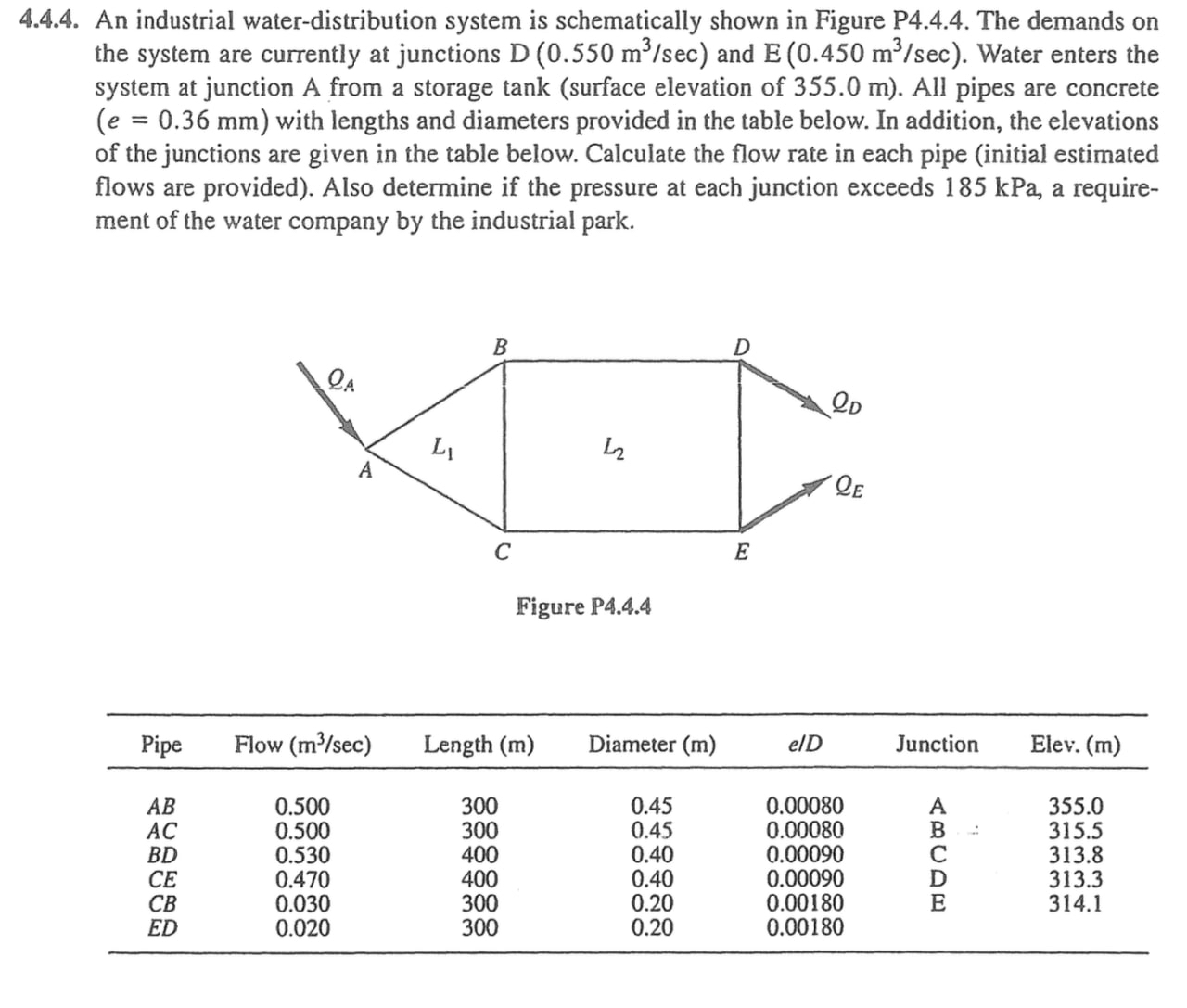
An industrial waterdistribution system is schematically shown in Figure P The demands on the system are currently at junctions and Water enters the system at junction A from a storage tank surface elevation of All pipes are concrete with lengths and diameters provided in the table below. In addition, the elevations of the junctions are given in the table below. Calculate the flow rate in each pipe initial estimated flows are provided Also determine if the pressure at each junction exceeds kPa, a requirement of the water company by the industrial park.
tablePipeFlow Length Diameter Junction,Elev.
Step by Step Solution
There are 3 Steps involved in it
1 Expert Approved Answer
Step: 1 Unlock

Question Has Been Solved by an Expert!
Get step-by-step solutions from verified subject matter experts
Step: 2 Unlock
Step: 3 Unlock