

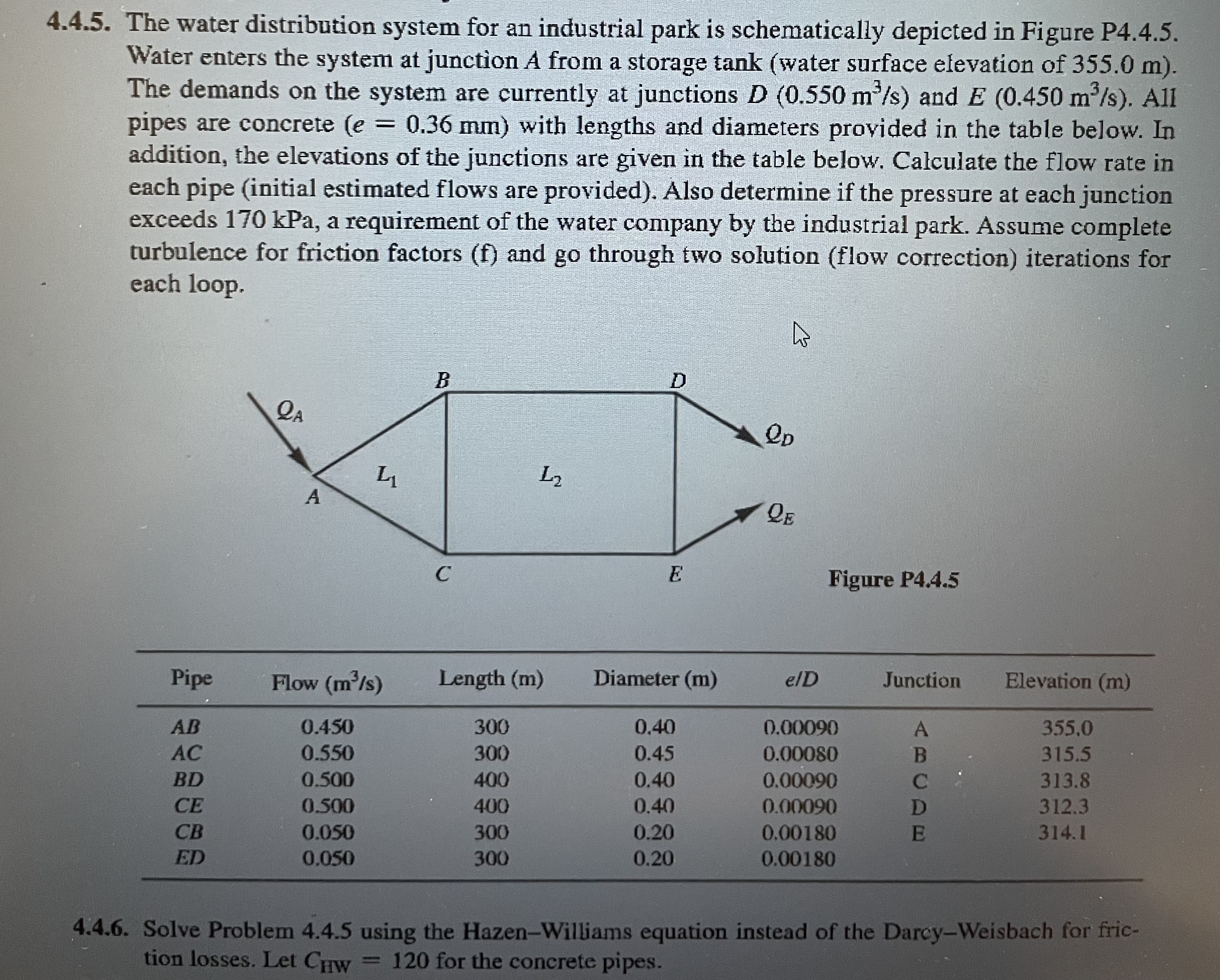
Question: 4 . 4 . 5 . The water distribution system for an industrial park is schematically depicted in Figure P 4 . 4 . 5
The water distribution system for an industrial park is schematically depicted in Figure P
Water enters the system at junction A from a storage tank water surface elevation of
The demands on the system are currently at junctions and All
pipes are concrete with lengths and diameters provided in the table below. In
addition, the elevations of the junctions are given in the table below. Calculate the flow rate in
each pipe initial estimated flows are provided Also determine if the pressure at each junction
exceeds kPa, a requirement of the water company by the industrial park. Assume complete
turbulence for friction factors and go through two solution flow correction iterations for
each loop.
Figure P
Solve Problem using the HazenWilliams equation instead of the DarcyWeisbach for fric
tion losses. Let for the concrete pipes.
Just do completely and thoroughly please.
Step by Step Solution
There are 3 Steps involved in it
1 Expert Approved Answer
Step: 1 Unlock

Question Has Been Solved by an Expert!
Get step-by-step solutions from verified subject matter experts
Step: 2 Unlock
Step: 3 Unlock