

Question: Excel Spreadsheet format does not matter as long as everything is clearly labeled. You have been asked to analyze the pipe network design in problem
Excel Spreadsheet format does not matter as long as everything is clearly labeled.
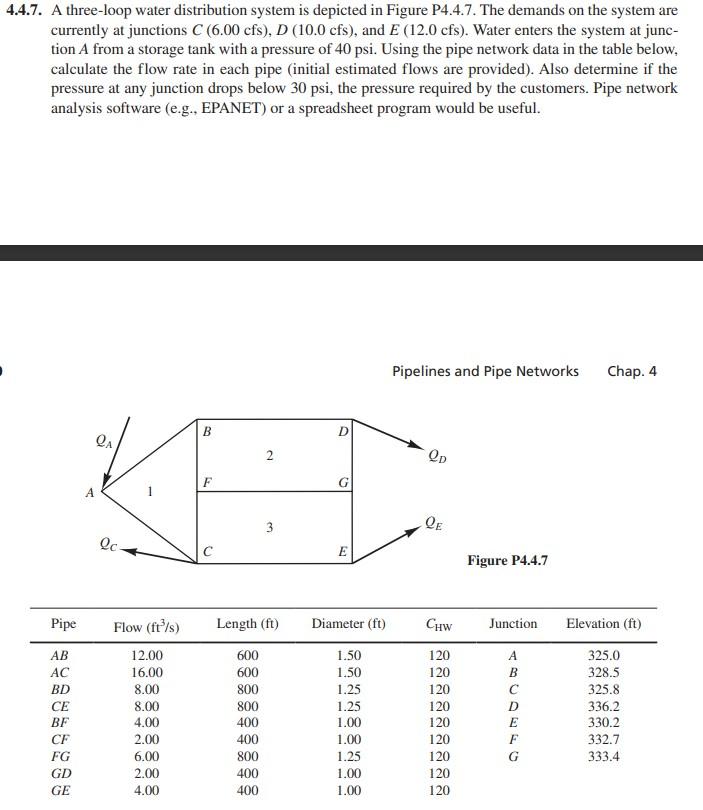
You have been asked to analyze the pipe network design in problem 4.4.7 in Houghtalen et al (2017). Write and execute a program in Excel to solve the problem but make the following alterations: (1) Use the Darcy-Weisbach friction head loss equation instead of the Hazen- Williams equation); (2) Do not assume fully-turbulent flow in the pipes. Instead, use the Swamee-Jain equation to determine the friction factor; (3) Make the material of pipes AB, AC, BF, and FC to be concrete (good joints, average) and the material of the remainder of the pipes to be galvanized iron; (4) Assuming the gage pressure drops to 36 psi at A, calculate the flow rates in all of the lines and the pressures at all of the nodes; (5) Without increasing the pressure at A, redesign the system to boost the pressures to meet the requirements at the three demand nodes. Specify the changes that you made in your design; (6) Provide a summary table containing the final computed flow rate, head loss, and pressure drop in every pipe;and (7) Re-solve the problem after placing a fully open swing type check valve in pipes AB and DG and a fully open globe valve in pipes FG and CE. 4.4.7. A three-loop water distribution system is depicted in Figure P4.4.7. The demands on the system are currently at junctions C(6.00 cfs), D (10.0 cfs), and E (12.0 cfs). Water enters the system at junc- tion A from a storage tank with a pressure of 40 psi. Using the pipe network data in the table below. calculate the flow rate in each pipe (initial estimated flows are provided). Also determine if the pressure at any junction drops below 30 psi, the pressure required by the customers. Pipe network analysis software (e.g., EPANET) or a spreadsheet program would be useful. Pipelines and Pipe Networks Chap 4 B D QA Op F 3 QE Qc E Figure P4.4.7 Pipe Length (ft) Diameter (ft) Chw Junction Elevation (ft) AB AC BD CE BF CF FG GD GE Flow (ft/s) 12.00 16.00 8.00 8.00 4.00 2.00 6.00 2.00 4.00 600 600 800 800 400 400 800 400 400 1.50 1.50 1.25 1.25 1.00 1.00 1.25 1.00 1.00 120 120 120 120 120 120 120 120 120 B D E F G 325.0 328.5 325.8 336.2 330.2 332.7 333.4 You have been asked to analyze the pipe network design in problem 4.4.7 in Houghtalen et al (2017). Write and execute a program in Excel to solve the problem but make the following alterations: (1) Use the Darcy-Weisbach friction head loss equation instead of the Hazen- Williams equation); (2) Do not assume fully-turbulent flow in the pipes. Instead, use the Swamee-Jain equation to determine the friction factor; (3) Make the material of pipes AB, AC, BF, and FC to be concrete (good joints, average) and the material of the remainder of the pipes to be galvanized iron; (4) Assuming the gage pressure drops to 36 psi at A, calculate the flow rates in all of the lines and the pressures at all of the nodes; (5) Without increasing the pressure at A, redesign the system to boost the pressures to meet the requirements at the three demand nodes. Specify the changes that you made in your design; (6) Provide a summary table containing the final computed flow rate, head loss, and pressure drop in every pipe;and (7) Re-solve the problem after placing a fully open swing type check valve in pipes AB and DG and a fully open globe valve in pipes FG and CE. 4.4.7. A three-loop water distribution system is depicted in Figure P4.4.7. The demands on the system are currently at junctions C(6.00 cfs), D (10.0 cfs), and E (12.0 cfs). Water enters the system at junc- tion A from a storage tank with a pressure of 40 psi. Using the pipe network data in the table below. calculate the flow rate in each pipe (initial estimated flows are provided). Also determine if the pressure at any junction drops below 30 psi, the pressure required by the customers. Pipe network analysis software (e.g., EPANET) or a spreadsheet program would be useful. Pipelines and Pipe Networks Chap 4 B D QA Op F 3 QE Qc E Figure P4.4.7 Pipe Length (ft) Diameter (ft) Chw Junction Elevation (ft) AB AC BD CE BF CF FG GD GE Flow (ft/s) 12.00 16.00 8.00 8.00 4.00 2.00 6.00 2.00 4.00 600 600 800 800 400 400 800 400 400 1.50 1.50 1.25 1.25 1.00 1.00 1.25 1.00 1.00 120 120 120 120 120 120 120 120 120 B D E F G 325.0 328.5 325.8 336.2 330.2 332.7 333.4
Step by Step Solution
There are 3 Steps involved in it

Get step-by-step solutions from verified subject matter experts